How To: BrewPi LCD Add-On

Homebrew Talk - Beer, Wine, Mead, & Cider Brewing Discussion Forum

Help Support Homebrew Talk - Beer, Wine, Mead, & Cider Brewing Discussion Forum:

This site may earn a commission from merchant affiliate links, including eBay, Amazon, and others.
Well, one month after the reorder to replace my boards that were lost by HK Post was entered - there's no sign that the order was processed. So, three months after I first ordered the boards, I figure this one is snakebit and I requested a refund. We'll see how that goes. I'll sit back a bit and watch the revisions and decide if I want to try again or just beg a spare board off another member...
 
Well, one month after the reorder to replace my boards that were lost by HK Post was entered - there's no sign that the order was processed. So, three months after I first ordered the boards, I figure this one is snakebit and I requested a refund. We'll see how that goes. I'll sit back a bit and watch the revisions and decide if I want to try again or just beg a spare board off another member...
I think you got caught up in the Chinese new year
 
I think you got caught up in the Chinese new year
I'm sure that's part of it, but I just decided to cut my losses on that order and try again later. DPCBs told me on Jan. 21 when they agreed to redo the order, that it wouldn't be run until after Feb. 5. More than two weeks after Feb. 5 and nothing but crickets, so time to move on.
 
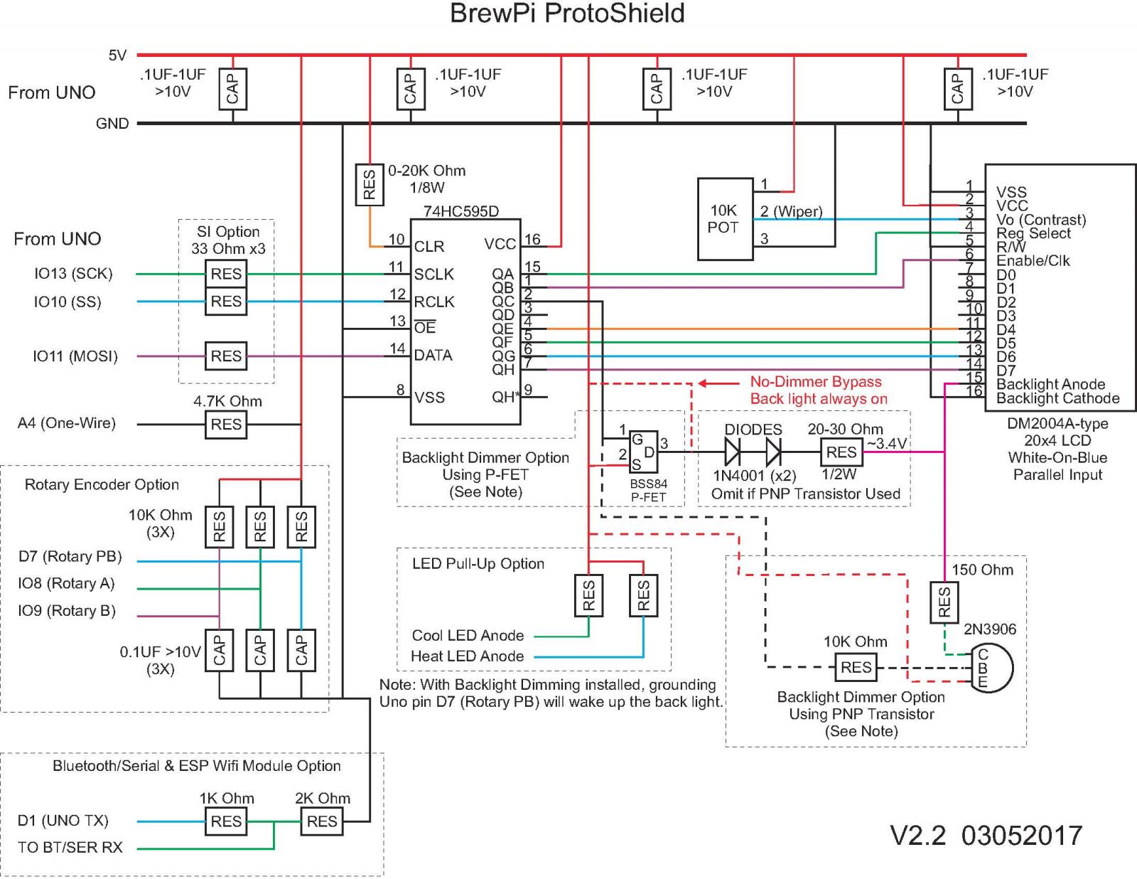
fwiw, I've updated my "generic" BrewPi shield schematic to fix a couple of errors...

Cheers!

brewpi_shield_rev_2p2.jpg
 
hah! That was one of the things I changed, as the part number is for a PnP while the drawing showed how you'd connect an NPN :)

Cheers!
 
Looks like he doesn't have a shield in there but it has an RJ11 jack on the side, so it could work for any of them, including the new v2.0 that we designed.

Don't tell anyone, but the new v2.0 shields arrived last night. I'm going to solder one up tomorrow and see what happens...
 
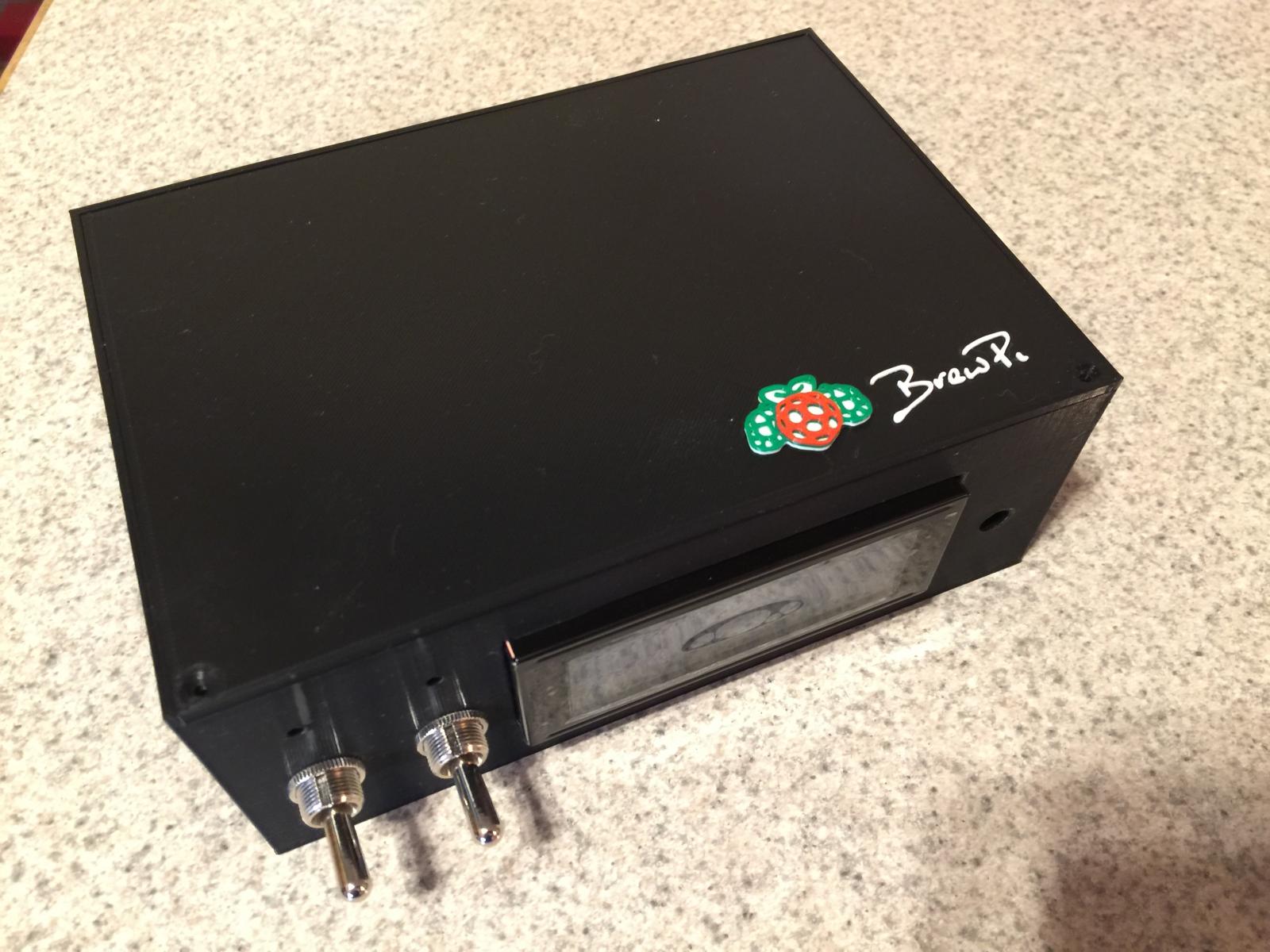
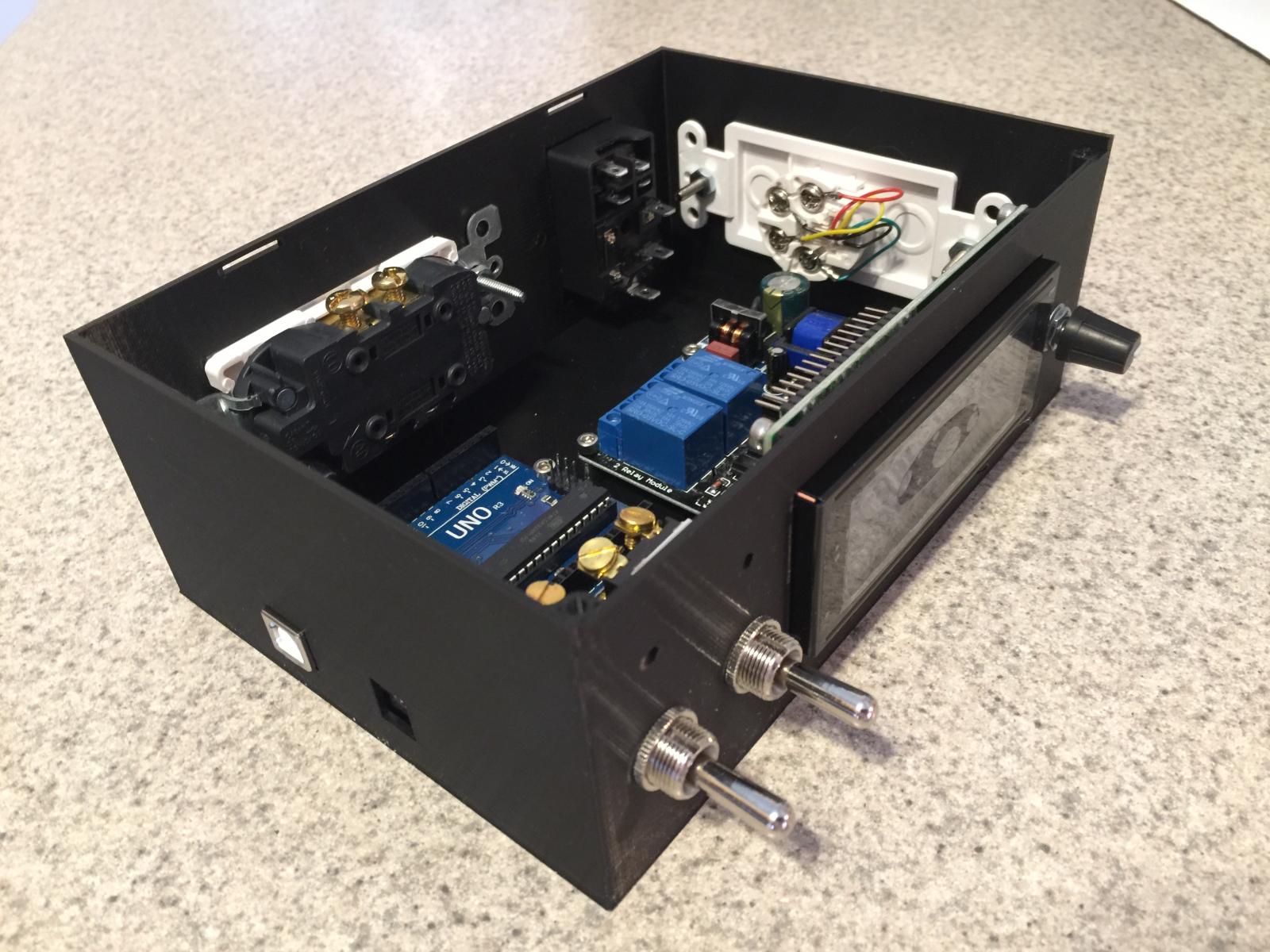
Box Dimensions are 185mm Wide x 130mm Deep x 70mm High. It was designed around the CadiBrewer 1st version shield, but should accommodate any of them.

ETA: I would imagine it would also accommodate the original handbuilt shield from early in the thread.
 
Case dimensions? And which shield?
I've attached the plans (and also uploaded them to Thingiverse) so you can see dimensions.

Looks like he doesn't have a shield in there but it has an RJ11 jack on the side, so it could work for any of them, including the new v2.0 that we designed.

Don't tell anyone, but the new v2.0 shields arrived last night. I'm going to solder one up tomorrow and see what happens...
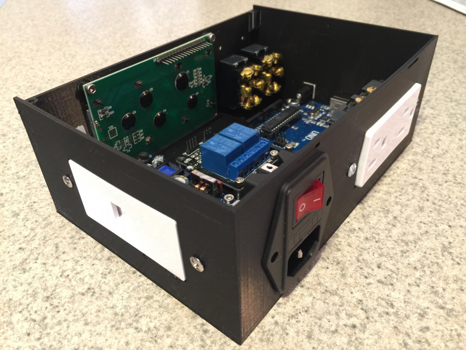
Yeah I forgot to plug the shield in for the pics but there's plenty of room for the v1.1 shields I have.

Don't the 2.0 shields use a different microcontroller?

View attachment Case Plan.pdf
 
Yes, v2.0 uses the Nano instead of the Uno. I realized last night that the box won't work as well for the new shield because you've got it perfectly set up for the inputs on the Uno to stick out the side of the enclosure. I really like your design. I can see myself printing at least two.

Kudos to the design team!
 
Just saw something on the enclosure that I had a question about. It looks like you've got a power supply inside for powering the Uno. I like the board that you've specd in the BOM. But if you've got the Uno oriented so that the USB and power jacks stick out the side of the enclosure, how do you access the power jack on the Uno from the inside?


Edit : are you just going to use the 5v and GND pins instead of the barrel jack? That would certainly work...
Yes sir - you got it. The idea was the connections would be available - like for testing before a complete wire-up, but my intent was to power from the bus. Of course a person could leave the power supply out and power it from the barrel or even the USB if they wanted.

Another option is to power the relay separately from the Uno ... choices. It was intended to allow just about anything.
 
Yes, v2.0 uses the Nano instead of the Uno.
I'd not considered going to the Nano ... mostly because the Uno works. It does seem like the Nano is a more compact package once you have it all said and done.

Looking at it ... it piggy-backs the Nano, shield, I2C, LCD, relay and BT module?

So, no "external" parts and the connections are USB for serial and power, probes, and the outputs from the relays?

The relay, rotary encoder, LEDs and probes attach via headers. The probes can also attach via an RJ11 jack. The bluetooth slots into a female header under the shield, though you could certainly use a pin header and attach it via dupont connectors.
 
The relay, rotary encoder, LEDs and probes attach via headers. The probes can also attach via an RJ11 jack. The bluetooth slots into a female header under the shield, though you could certainly use a pin header and attach it via dupont connectors.

Do you have a pic of how the 2 temp sensor cables are joined to be crimped to the RJ11 cable that plugs into the RJ11 socket?
 
Do you have a pic of how the 2 temp sensor cables are joined to be crimped to the RJ11 cable that plugs into the RJ11 socket?

Have you soldered your sensors to an RJ11 cable yet?

Here's the general idea, but double check the RJ11 pinout. I think it should be 1-Vdd, 2-Data and 3-Gnd. Pin 4 on the RJ11 is not connected.

http://www.homenetworkenabled.com/content.php?179-Making-your-own-Temp-1Wire-Temperature-sensor-with-RJ11-interface

The cables can be any length, then hook them up to an RJ11 splitter/joiner as shown in day tripper's post.

Once you have a bunch of 1-wire devices attached to RJ11 plugs then troubleshooting and reconfiguring them is easy. Just plug and play. You'll need a handful of splitters and some RJ11-RJ11 straight-through cables, but you can buy them premade (for US telephones) or buy a bag of RJ11 plugs, a reel of 4-core flat telephone cable, and a crimping tool and you're all set.
 
Last edited:
Don't order the new v2.0 boards yet. I need to make a change to the bluetooth header layout. I have it 180 degrees from where it needs to be. Let me finish testing all of the functions this weekend and I'll put up revised board files for public consumption.
 
Sweet that works. wouldn't it be cheaper to just add another RJ11 port than have to buy the adapter? its nice to having it all directly plugging in without plugging in a extra adapter :)
 
Sweet that works. wouldn't it be cheaper to just add another RJ11 port than have to buy the adapter? its nice to having it all directly plugging in without plugging in a extra adapter :)

Cheaper for whom? Nicer compared to what?

Since you are buying the components yourself it ought to be a wash. Buy two sockets for the box, or buy one​ socket and one splitter.

But, you're missing the point. The point is that the 1-wire bus can have as many devices on it as you like. It is not limited by the number of sockets on the box. Also, you can make your wiring simpler.

If your box was, say, 1m from the fermenter you could assemble two sensors with 1m cables and plug them in to the box (if the box has two sockets).

However, you could have two sensors with short cables, say, 20cm, or random unrelated lengths. With a single socket and a splitter you can have a single 1m cable from the box to the fermenter, add the splitter, then connect the two sensors to the splitter.

Furthermore, if you want to add a third sensor (room temperature?) you just need another splitter, not another socket on the box. In my opinion that's nicer.
 
When I thought up the nano backpack the idea was for it to be small and sleek. I think the board cadi put out is pretty close to what I envisioned. 2 temp probe ports would be nice. but it's not a deal breaker. the boards look quite small and therefore affordable. personally I would have made the backpack roughly the same size as the lcd pcb so I could space out the components and make porting out the features a little easier. but small is the key thing here. I would have put the barrel jack on the other side though. since its in the middle of the lcd like this. And not very accessible if you were to 3d print an enclosure for this setup. the first time I envisioned a small footprint brewpi like this, I was thinking of building an all-in-one ferment jacket. something you could stick in just about any cold space and then use only a heat wrap for temp control. with a single relay board. but that was just an idea I had years ago. but I learned how versatile the tiny nano could be and I almost switched over completely to nanos over unos. who knows maybe one day I'll take to a pcb design app and try my hand at coming up with a design. in the mean time, good job on the version 2 boards. can't wait till they are finalized.
 

Latest posts

Back
Top