How To: BrewPi LCD Add-On

Homebrew Talk - Beer, Wine, Mead, & Cider Brewing Discussion Forum

Help Support Homebrew Talk - Beer, Wine, Mead, & Cider Brewing Discussion Forum:

This site may earn a commission from merchant affiliate links, including eBay, Amazon, and others.
Were you guys envisioning that there would be one RJ11 connector on the board and that you'd splice your probes together outside of the enclosure and bring one RJ11 cable into the enclosure? Or were you envisioning three RJ11 connectors on the board, one for each probe?.

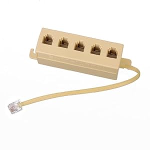
RJ11 can be split with a normal phone splitter. This is what I am doing now.
 
I have a question for those of you who will be using the new Nano board with an RJ11 connector on board:

Were you guys envisioning that there would be one RJ11 connector on the board and that you'd splice your probes together outside of the enclosure and bring one RJ11 cable into the enclosure? Or were you envisioning three RJ11 connectors on the board, one for each probe?

I was assuming that there would be only one connector on the board, but someone wiser than I (read everyone, but in particular day_trippr), thought it good to verify that before I finalize the design, and I wholeheartedly agree!

Let me know what you were envisioning so I can get this done.
I was thinking one RJ11 on the board and then splitting on the outside with a phone jack.
31DUEAmj%2B9L._SY300_.jpg
 
Maybe a double rj11 jack on the board (since I have like 20 of those lying around)…lol. and maybe even a temp sensor built right into the board to monitor room temps
 
Maybe a double rj11 jack on the board (since I have like 20 of those lying around)…lol. and maybe even a temp sensor built right into the board to monitor room temps
I like the idea, but do the components (like power supplies and processors) generate enough heat to make that a wasted effort?
 
I like the idea, but do the components (like power supplies and processors) generate enough heat to make that a wasted effort?

Yes, they do, especially if you build your enclosure with the power supply inside so the only power source coming in is the AC line.
I just did a thermal scan of one of my minions and there was a ~10°F gain over ambient - and the LCD hadn't been on in hours.

Putting a "room temperature" sensor in such an environment would be an epic fail...

Cheers!
 
I have a question for those of you who will be using the new Nano board with an RJ11 connector on board:

Were you guys envisioning that there would be one RJ11 connector on the board and that you'd splice your probes together outside of the enclosure and bring one RJ11 cable into the enclosure? Or were you envisioning three RJ11 connectors on the board, one for each probe?

I was assuming that there would be only one connector on the board, but someone wiser than I (read everyone, but in particular day_trippr), thought it good to verify that before I finalize the design, and I wholeheartedly agree!

Let me know what you were envisioning so I can get this done.

Just one. Unless you have a lot of space and want to add more for the sake of it.

It's neat to have a single cable from the enclosure to the sensors, using various splitters as required. It also makes it easier if someone has bought waterproof temperature probes that are too short- just add an RJ11 plug and extend it with a splitter and back to the box.

My waterproof sensor (beer temperature) is hooked up to a 3.5mm plug, without the plastic housing, just some heatshrink. This makes the plug smaller than the diameter of the sensor so it will go through the hole in the vessel lid from the inside. Then I have a 3.5mm socket to RJ11 plug pigtail to connect it to the nearest splitter.

All of my 1-wire devices have RJ11 plugs on them, and I have a bunch of splitters and couplers (and a roll of flat telephone cable and an RJ11 crimping tool). It's literally plug-and-play.

Edit: For my own reference (so I can look back at this post and remember what I did) my 3.5mm plug is wired as described here:
https://learn.openenergymonitor.org/electricity-monitoring/temperature/DS18B20-temperature-sensing

Tip: DQ
Ring: VDD
Sleeve: GND
 
I like the idea, but do the components (like power supplies and processors) generate enough heat to make that a wasted effort?


Just 3 pins on the board, doesn't have to actually be soldered to the board
 
For the V2.0 layout I recommended Cadibrewer include a three pin header behind the RJ11 as an alternative 1-wire bus connector, thinking about enclosure implementations.

Also an option (by moving a resistor) to enable a non-blanking LCD, as some have commented they prefer that.

Cheers!
 
I have a question for those of you who will be using the new Nano board with an RJ11 connector on board:

Were you guys envisioning that there would be one RJ11 connector on the board and that you'd splice your probes together outside of the enclosure and bring one RJ11 cable into the enclosure? Or were you envisioning three RJ11 connectors on the board, one for each probe?

I was assuming that there would be only one connector on the board, but someone wiser than I (read everyone, but in particular day_trippr), thought it good to verify that before I finalize the design, and I wholeheartedly agree!

Let me know what you were envisioning so I can get this done.

I'd do 2x RJ11 ports so there is 1 port per probe. maybe another 3rd if someone does not want 2 and wants to split the wire out off one. either that or make jumper contacts so you can direct the circuit before it hits the 2nd port to the first point.

will v1.2 and v 2.0 have holes to mount the encoder direct to the board?
 
V1.2 is only a modest change that replaces the SMT FET with a through-hole PNP transistor circuit, to accommodate those with nascent soldering skills...

Cheers!
 
Just 3 pins on the board, doesn't have to actually be soldered to the board

For the V2.0 layout I recommended Cadibrewer include a three pin header behind the RJ11 as an alternative 1-wire bus connector, thinking about enclosure implementations.

Also an option (by moving a resistor) to enable a non-blanking LCD, as some have commented they prefer that.

Cheers!
I like!
 
Pfet was probably the easiest part…lol

View attachment 387154

I used low temp solder past and an oven for 15 minutes.

Definitely looks a lot cleaner than all my other solder jobs…

View attachment 387156

Came out looking nice though.

Did you go back and solder a header on the six ICSP pins? The power and ground for the shift register are connected to those pins so the LCD won't work without it.
 
Yeah I'm still waiting for the female headers to come in

Also it appears that I really only need 2 of the 6 pins, so I'll just put one 3 pin header on there
 
Well, after waiting more than two months for my boards from Dirty PCBs - it appears that they are well and truly lost by HK Post. DPCBs has volunteered to replace the order, however that will have to wait until they get over their Spring Festival hangover - around February 5th.

If you order from DPCBs, upgrade the shipping to DHL to get a tracking number.

I ordered a batch of boards last week. Hopefully they won't take forever.
 
did we ever come up with a proper standard header layout for the encoder?
 
I dont know if its been brought up before, but i just easily stabbed a hex file onto my arduino from windows using arduino itself. super easy and it makes initial setup way easier as you dont need to worry about it when it comes time to start setting up the boards. I just used a simple cmd line process to invoke avr dude. you will need to make the appropriate changes for your user name, com port and hex file location, but here is the line of code i used today on a win10 machine.

Code:
"C:\Users\UserName\AppData\Local\Arduino15\packages\arduino\tools\avrdude\6.3.0-arduino6/bin/avrdude" -C"C:\Users\UserName\AppData\Local\Arduino15\packages\arduino\tools\avrdude\6.3.0-arduino6/etc/avrdude.conf" -v -patmega328p -carduino -PCOM4 -b115200 -D -Uflash:w:"C:\Users\UserName\Downloads\brewpi-arduino-uno-revC-0_2_10.hex":i

hope it can help someone

Is that easier than using Xloader?
 
it is since i dont know what xloader is... and i literally just programmed 4 unos in about 1 minute. since all mine will be on bluetooth, i find this is easier just simply because i haven't setup the pi yet, arduino is already installed, and i needed to just see that they were all working through serial terminal since i have bt built into my win10 machine its as easy as setting up one shield and just plugging in different arduinos to make sure i can receive serial data over bt. now all i need to do is setup the pi and get a few more hc-05s programmed, and finally finsh soldering the other 3 boards i have already. but this basically is a proof that my soldering is sufficient and that all my chinese unos are functional
 
it is since i dont know what xloader is... and i literally just programmed 4 unos in about 1 minute. since all mine will be on bluetooth, i find this is easier just simply because i haven't setup the pi yet, arduino is already installed, and i needed to just see that they were all working through serial terminal since i have bt built into my win10 machine its as easy as setting up one shield and just plugging in different arduinos to make sure i can receive serial data over bt. now all i need to do is setup the pi and get a few more hc-05s programmed, and finally finsh soldering the other 3 boards i have already. but this basically is a proof that my soldering is sufficient and that all my chinese unos are functional

Xloader is a small freeware program that does the same thing. You attach your Uno to your laptop via USB and load the hex file. I've programmed all of my builds that way. I haven't had much luck using the BrewPi software to program the Uno.
 
Another question for the group on the v2.0 board. With day_trippr's help and Ame's wiring scheme for the RJ11 connector, I've got the probes and door function set up. Does anyone use the light or fan functions built into BrewPi? If so, how, and would we want those somewhere on the shield?
 
For those unfamiliar with the more obscure BrewPi capabilities:

- the Fan circuit is an output and is enabled whenever Cool or Heat modes are active.

From my experience running the fan only when Cool or Heat mode is active is not optimal wrt preventing stratification. I run my ferm fridge fans full time, same with my keezer.

- the Light circuit is an output and is intended to act as a heater.
One might ponder the thermal gain provided by a fridge interior light, considering they're generally surrounded by thermo-formed plastic.

Elco's Arduino shield provided separate FETs enabled by Arduino pin A5 and digital IO 6 to spin a small 5V DC fan, or a relay or SSR for something more substantial, and a relay or SSR for the fridge light. I wouldn't burden the 2.0 shield with either, but I would break out the two pins, as once the Nano is plugged in getting to them ain't happening without flying leads...

Cheers!
 
You can use the light as just a simple light that comes on when you open the door. I do use door sense pins and I have contemplated whether of not to just use the door sense to sync a relay instead of the actual light control pin on the arduino. it does work either way. you can just add pinout a for potential headers for pins 2,3,4. hell you could even add them next to the relay pins for those of us that use 4-8 way relay boards…
 
Also you can redefine what pin 3 or 4 does…. One can be defined as chamber fan and it can come on with 5 and 6 as day described without the need for extra fets.
 
Almost done with the shield. Just want to make sure I get this right so that it has as much of what people want as possible.

I'm pulling header pins for the IO pins on the Arduino associated with the Light and Fan functions to allow people to utilize those if they wish.

For the Door function, I'm integrating that into the RJ11 connector in the wiring scheme that Ame posted:

1: NC
2: 3V3
3: DQ
4: GND
5: DOOR
6: NC

To use the Door function, do you wire your door sensor switch to Door and GND or Door and 3v3? I would assume GND but assuming hasn't treated me well thus far.
 
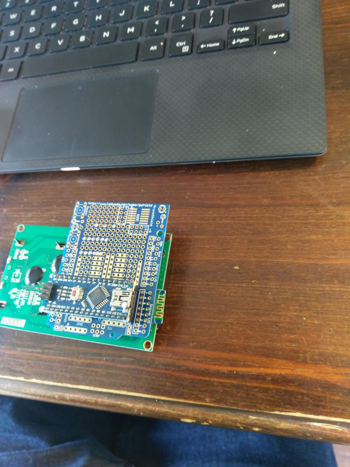
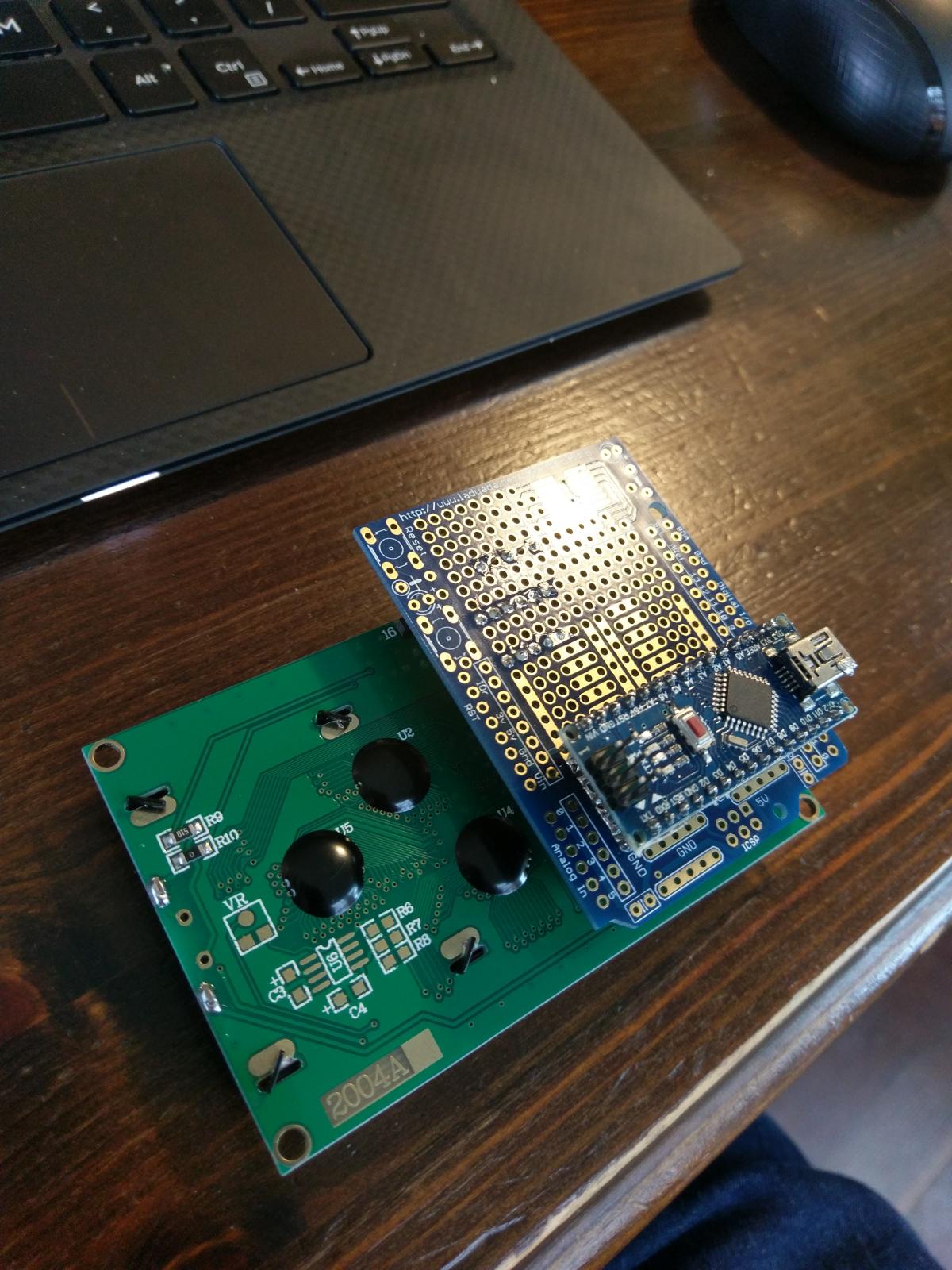
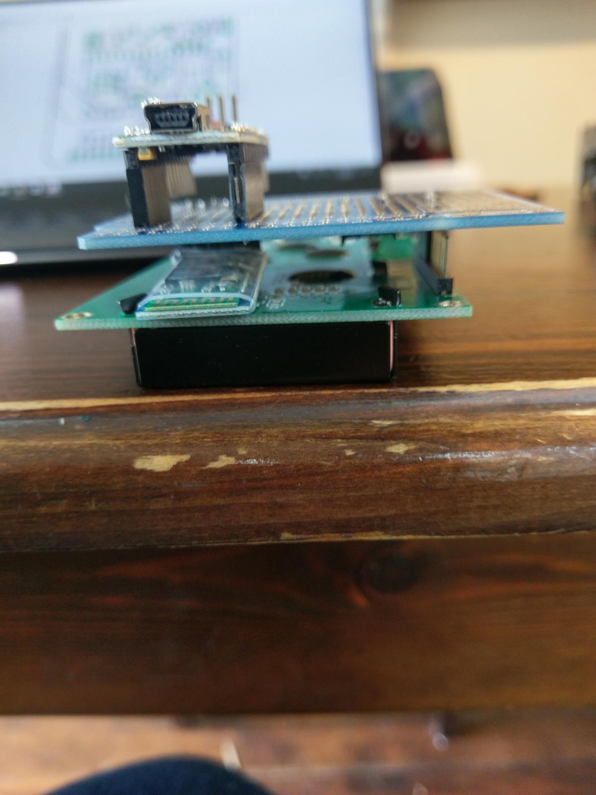
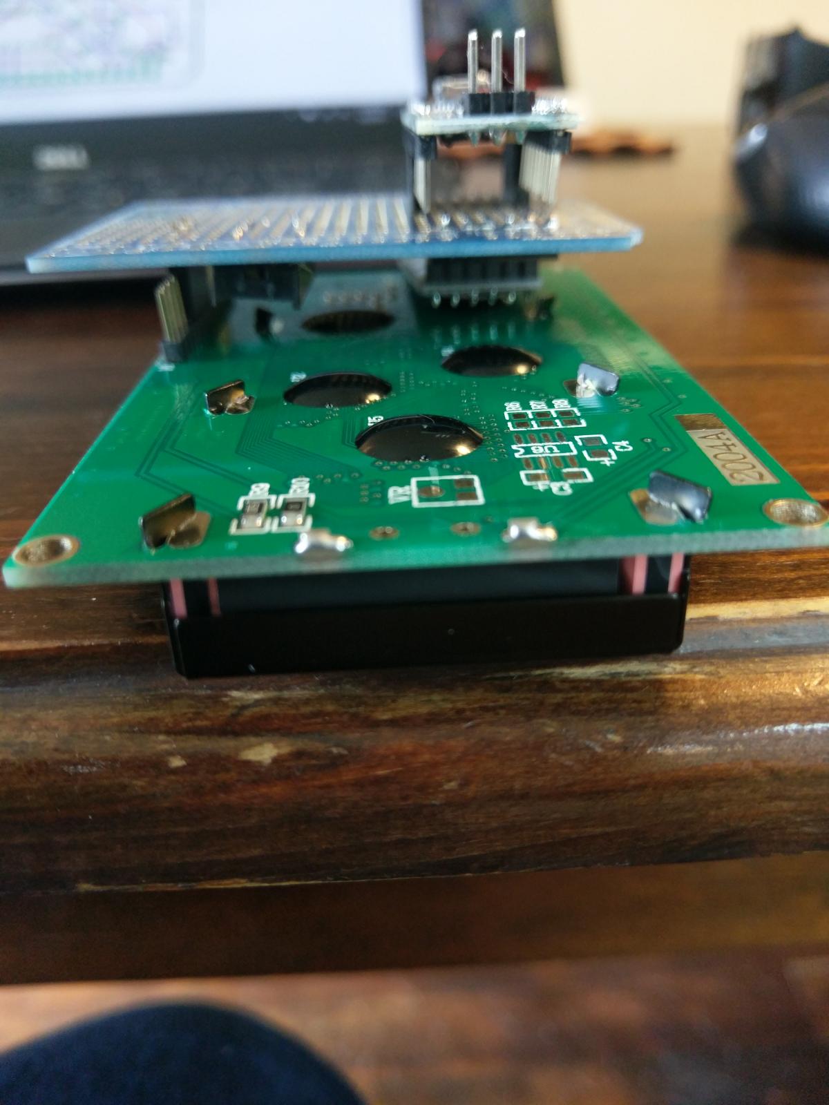
Here's a mock-up of how v2.0 will come together. Keep in mind that the proto shield that I sacrificed is longer and sticks out over the top of the LCD. The actual shield lines up with the top of the LCD. Also, the bluetooth radio antenna will stick out a bit further for better reception - I was limited on the proto shield for placement holes, so this was as close as I could approximate the location.

For space purposes, I had to put some caps and resistors under the Arduino, so you won't be able to solder the Arduino directly to the shield. I would think that most would want to use headers anyway, so this shouldn't be much of a sacrifice. That being said, one could solder the caps and resistors on the underside of the board instead of on top and you could still achieve soldering the Arduino directly to the shield. The downside to that (other than the obvious that you'd never be able to decouple your Arduino should you want to) is that the bluetooth module sits in the same area, so there may be minor clearance issues. If you were to keep the plastic wrapper around your bluetooth module, there shouldn't be any issues with metal touching metal.

I don't have the barrel connector for power input or an RJ11 jack yet, so I couldn't mock those up.

Anyone see anything that would be a deal-killer here?

IMAG0120.jpg


IMAG0121.jpg


IMAG0122.jpg


IMAG0123.jpg
 
Almost done with the shield. Just want to make sure I get this right so that it has as much of what people want as possible.


I'm pulling header pins for the IO pins on the Arduino associated with the Light and Fan functions to allow people to utilize those if they wish.


For the Door function, I'm integrating that into the RJ11 connector in the wiring scheme that Ame posted:


1: NC

2: 3V3

3: DQ

4: GND

5: DOOR

6: NC


To use the Door function, do you wire your door sensor switch to Door and GND or Door and 3v3? I would assume GND but assuming hasn't treated me well thus far.


IO > door switch > gnd
 
Here's a mock-up of how v2.0 will come together. Keep in mind that the proto shield that I sacrificed is longer and sticks out over the top of the LCD. The actual shield lines up with the top of the LCD. Also, the bluetooth radio antenna will stick out a bit further for better reception - I was limited on the proto shield for placement holes, so this was as close as I could approximate the location.


For space purposes, I had to put some caps and resistors under the Arduino, so you won't be able to solder the Arduino directly to the shield. I would think that most would want to use headers anyway, so this shouldn't be much of a sacrifice. That being said, one could solder the caps and resistors on the underside of the board instead of on top and you could still achieve soldering the Arduino directly to the shield. The downside to that (other than the obvious that you'd never be able to decouple your Arduino should you want to) is that the bluetooth module sits in the same area, so there may be minor clearance issues. If you were to keep the plastic wrapper around your bluetooth module, there shouldn't be any issues with metal touching metal.


I don't have the barrel connector for power input or an RJ11 jack yet, so I couldn't mock those up.


Anyone see anything that would be a deal-killer here?


So are you planning on having the encoder mount straight to the board? that setup is very close to what I did for the protoboard mock up I did a few years backView attachment ImageUploadedByHome Brew1486160843.465781.jpgView attachment ImageUploadedByHome Brew1486160900.320541.jpg

No lcd or anything fancy. something it was working on for my mini- fridge. I made one similar to this to use in my rpints setup.
 
So are you planning on having the encoder mount straight to the board? that setup is very close to what I did for the protoboard mock up I did a few years back.

Nope. There's a header for the encoder. The board sits behind the LCD, so there's not a way to mount the encoder where you'd be able to get to it from the front of your enclosure. Plus, there's more flexibility for all types of builds if the encoder isn't on board. With the layout as I have it now, the only requirement for your enclosure is that it needs to be wide enough to accommodate the LCD board plus a bit for the Bluetooth hanging over. That leaves a lot of flexibility for all types of enclosures.

I saw your setup in the older posts. I like it.
 
When it comes to building an lcd backpack, remember you have the entire size of the lcd pcb to work with. it may actually be slightly more beneficial if the backpack pcb were slightly larger than the lcd pcb so it can be mounted more easily.
 
Just a heads up. I just received my knock off Nanos in anticipation of the new 2.0 shield and sure enough they don't past the blink test .looks like i'll need to load the boot loader. Currently searching for the best procedure on how to do it.
 

Latest posts

Back
Top