Help! Chest Freezer wiring to STC 1000 Controller

Homebrew Talk - Beer, Wine, Mead, & Cider Brewing Discussion Forum

Help Support Homebrew Talk - Beer, Wine, Mead, & Cider Brewing Discussion Forum:

This site may earn a commission from merchant affiliate links, including eBay, Amazon, and others.

esahc161

Member
Joined
Apr 23, 2014
Messages
6
Reaction score
0
Location
Indianapolis
Hello everyone,

I am a novice homebrewer, about two years, and I have just recently tried to construct a Keezer to start kegging my beer. I have built the collar and am about done but I have been having trouble with the wiring part....I am trying to identify which wires go where (I have absolutely no experience with wiring things). I understand the green grounded wires and white power wires, but my manual and the actual wires on my chest freezer are not labeled well at all.....Pics are included of every angle of my freezer's motor and wires and also of the temperature controller I have purchased.

Questions!
1. In picture #1 and #8, I am not sure which metal piece is the actual device taking the temperature readings in my freezer (it had a 1 to 8 scale but the lowest was still freezing!).

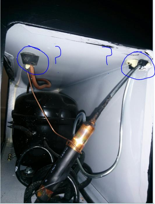
2. In picture #1 I have taken off the white and black wires from the green light that glowed when my freezer was turned on. But the device underneath it (better view in picture #5 or even #2) I have no idea what it is.....

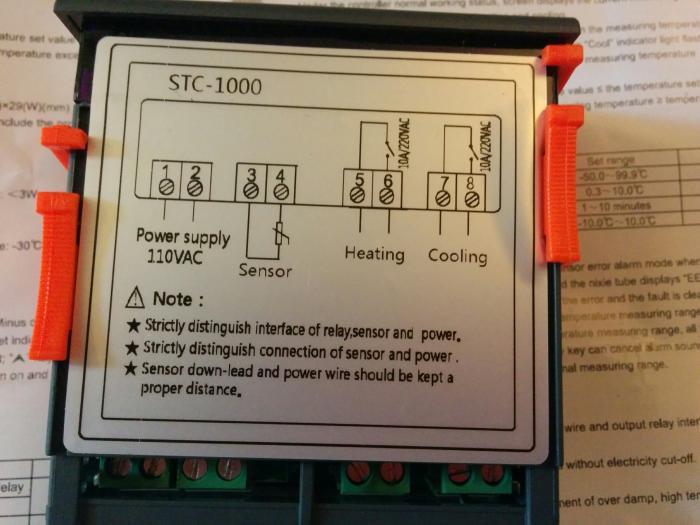
3. Picture #3 I do not understand what most of the wires mean (as in where the power supply/sensor/heating/cooling wires are....see picture #6 for the STC controller and wiring diagram.


I have been trying to read and watch youtube videos on how to do this but I cannot find the freezer that I have!!! I have 4 beers sitting in the carboys ready to be kegged and I really do not want to bottle!! Any help would be greatly appreciated.


Pictures Index:
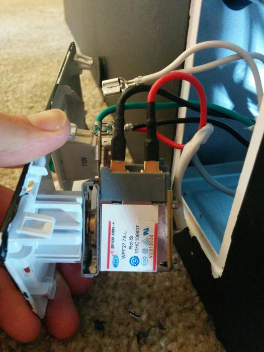
#1 --> Inside of the front panel.
#2 --> Box thing attached to panel?
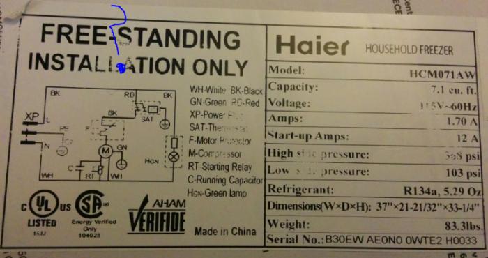
#3 --> Wiring guide that came with Freezer Manual.
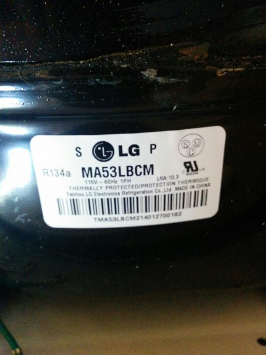
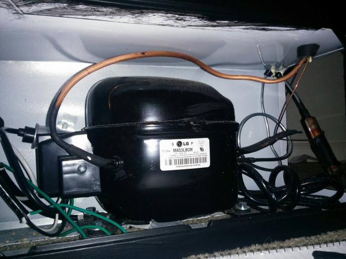
#4 --> Tag to Freezer Motor
#5 --> another view of #2
#6 --> STC Controller
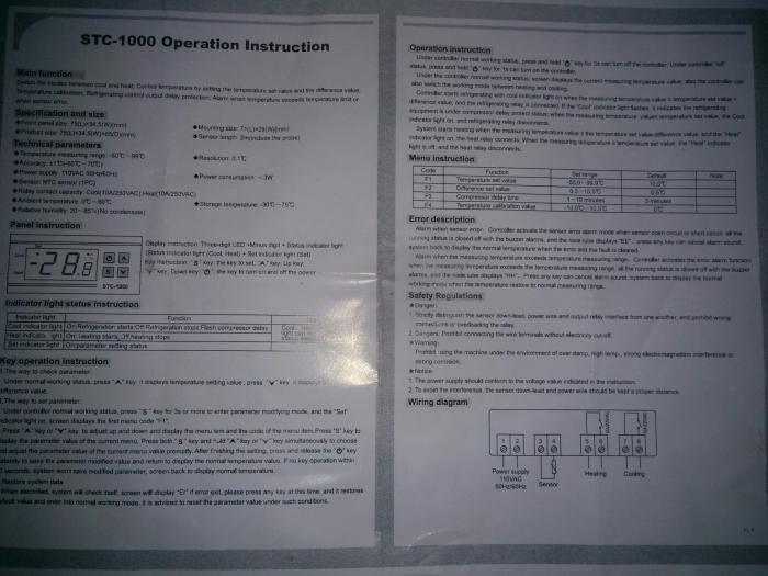
#7 --> STC Controller Directions
#8 --> Back of freezer
#9 --> Side of Freezer

1.jpg


2.jpg


3.jpg


4.jpg


5.jpg


6.jpg


7.jpg


8.jpg


9.jpg
 
If you dont understand the wiring of your freezer why are you taking it apart?

You dont need to modify your freezer to use it with a STC1000.

Make your STC-1000, wire it to a Power outlet and extension cord you get a HDepot, and then plug your Freezer into the outlet on the STC and your done..and there's dozens of tutorials on just doing a standard STC-1000. There's really no benefit to hard wiring it to your freezer except potentially maybe saving space? I dont know even that's subjective.

Follow the build here
https://www.homebrewtalk.com/f51/stc-1000-ebay-temperature-controller-build-330427/

And you can have it up and running in a few hours.
 
The build link you referenced involves building an external controller that the freezer is then plugged into.

Since you asked for an explanation of the photos and components, I'll give it a try.

The "box thing" in the 1st, 2nd and 4th photo is the existing thermostat. It is labeled SAT on the schematic in the 3rd photo. It has a red and black wire attached. It also has a capillary tube covered in white a white vinyl shroud which leads to the existing temperature sensing bulb.

Essentially, the cooling switch inside of the STC1000, between terminal 7 & 8, will replace this thermostat, albeit external to the freezer. If the STC1000 was being mounted into the freezer, the black and red wires would be removed from the existing thermostat and attached/jumpered to terminals 7 & 8. If you want to simply bypass the existing thermostat, although not entirely necessary, the black and red wires would be jumpered together.

The last two photos show the compressor portion of the refrigerant system. Each of the two sets of tubes go to coils. One is the evaporator coil, which absorbs heat from the interior. The other is the condensor coil, which dissipates heat through the skin of the unit. Any penetration of the walls of the unit has the potential to damage these coils and lines.
 
If you dont understand the wiring of your freezer why are you taking it apart?

You dont need to modify your freezer to use it with a STC1000.

Make your STC-1000, wire it to a Power outlet and extension cord you get a HDepot, and then plug your Freezer into the outlet on the STC and your done..and there's dozens of tutorials on just doing a standard STC-1000. There's really no benefit to hard wiring it to your freezer except potentially maybe saving space? I dont know even that's subjective.

Follow the build here
https://www.homebrewtalk.com/f51/stc-1000-ebay-temperature-controller-build-330427/

And you can have it up and running in a few hours.


I haven't really taken it apart (just disconnected 2 wires for better pictures). Also, I am not trying to modify it, only want to get it running like you said a 'standard STC-1000' set up.

The problem I am having is knowing which wires are which. The Thread you linked shows a diagram with blue wires as the cooling ones.....My pictures show that I only have black/red/white/green.......

Thank you for the response though, I am closer to figuring it out!
 
I know right. I had seen a diagram that had purple wires in the drawing... BLEW.. MY.. MIND!!!

j/k i the color of the wires in the diagram are not important and only colored red and blue to show that they are hot and cold, respectively. An external build is much more simple, but i get that some folks flush mount these in the collar and it's better to hack the freezer for that I guess.
 
Like Fuzze says, build the STC1000 (or buy one already made) and plug it into the wall, plug your freezer into the STC1000 box and run the thermometer into the freezer and set your desired temp. It's that simple.
 
The build link you referenced involves building an external controller that the freezer is then pluged into.

Since you asked for an explanation of the photos and components, I'll give it a try. It would have been a little easier if all existing connections had been left intact.

The "box thing" in the 1st, 2nd and 4th photo is the existing thermostat. It is labeled SAT on the schematic in the 3rd photo. It has a red and black wire attached. It also has a capillary tube covered in white a white vinyl shroud which leads to the existing temperature sensing bulb.

Essentially, the cooling switch inside of the STC1000, between terminal 7 & 8, will replace this thermostat. If the STC1000 was being mounted into the freezer, the black and red wires would be removed from the existing thermostat and attached/jumpered to terminals 7 & 8. If you want to simply bypass the existing thermostat, the black and red wires would be jumpered together.

The last two photos show the compressor portion of the refrigerant system. Each of the two sets of tubes go to coils. One is the evaporator coil, which absorbs heat from the interior. The other is the condensor coil, which dissipates heat through the skin of the unit. Any penetration of the walls of the unit has the potential to damage these coils and lines.


Sorry, I guess I did place a build link that shows directions to 'modify the freezer and build an external controller that the freezer would plug into' (so future viewers disregard that link....edited it out). I will try to wire it again after work tonight, I appreciate the explanations of the components. Thanks for the response!
 
I haven't really taken it apart (just disconnected 2 wires for better pictures). Also, I am not trying to modify it, only want to get it running like you said a 'standard STC-1000' set up.

The problem I am having is knowing which wires are which. The Thread you linked shows a diagram with blue wires as the cooling ones.....My pictures show that I only have black/red/white/green.......

Thank you for the response though, I am closer to figuring it out!

None of those wires in the diagram in the link i posted are from your fridge...they are all wires you must do yourself.

You then plug your freezer into the cold socket, and plug the other end of the STC into the wall.

The colors are meaningless in the picture other than color coding, you could make them all bright orange if you wanted and it would still work.

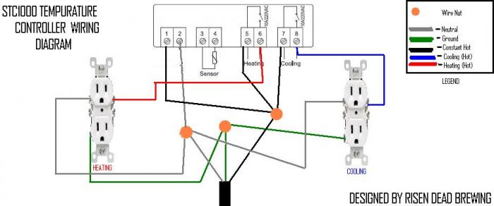
The bottom Green/White/Black wires come from an extension cord you chop the Female end off of. The male end of that extension cord is then what you plug into the wall, you cut the female end off, strip the green/white/black wires and plug them into the STC as shown.

As a tip, I also recommend chopping 2-3" lengths of wire off of the female end, like 4-5 sections. You can then pull the Green/White/Black wires out of the sheathing and use them for the other necessary wires shown in the diagram. Then when you have that done wire in the remaining length of extension cord to the STC1000.

That diagram shows it using two outlets, you can do it just with one double outlet, you dont need to worry about heating in a keezer.
 
Hello again,

Sorry it has been awhile, but I have wired my STC controller per the diagram given. The pictures attached are the diagram I used and my wiring (one a little bit closer). The STC controller turns on when I plug it into the wall, but when I plug my fridge into any of the sockets, it does not turn on. How can I fix this?

Also, I tried your suggestion of just one power outlet first, but when this problem occurred I figured maybe a second one was needed for some reason.....same result.

Help! beer is still sitting there haha. Thanks again for all the help.

0.jpg


0 (1).jpg


0 (2).jpg
 
It looks to me like you only have the Cooling Hot and the ground set up on the cooling side. You need to run the neutral wire to the cooling socket.
 
It looks to me like you only have the Cooling Hot and the ground set up on the cooling side. You need to run the neutral wire to the cooling socket.

You were right I forgot the neutral wire on the right socket, I have since added that and I am still getting the same result....What else could be wrong?
 
Do you have your temperature probed connected? The temperature of the probe will have to go below the cooling set point before it provides power to your electrical outlet.
 
Also, when the STC-1000 is plugged in and the temp probe is registering a temp higher than the programmed value, there is a delay before the cooling circuit comes on. You will see a red light flashing in the corner of the numeric display until that delay passes (3 minutes is the default, if I recall correctly), then the light will go solid and the cooling circuit will be live. So, if the light is flashing, wait until it is solid before deciding the cooling circuit isn't working.
 
I prefer to remove the thermostat and tie those wires into the cooling relay contacts of the ST-1000. That way you still have a light when you open the door. You also keep the defrost mode.
 
It finally worked! There were two problems: I did not have the STC settings just right and the outlet I was using was only giving me 30 volts (so I guess that was enough to tun on the controller but not the fridge). I just plugged the STC into a different socket giving out 125 volts a voila!

Thanks everyone for the help. Excited to keg all of my beers this weekend :).
 
Back
Top