Control Panel Wiring Diagram and Power

Homebrew Talk - Beer, Wine, Mead, & Cider Brewing Discussion Forum

Help Support Homebrew Talk - Beer, Wine, Mead, & Cider Brewing Discussion Forum:

This site may earn a commission from merchant affiliate links, including eBay, Amazon, and others.

Liveforliving

Well-Known Member
Joined
Aug 3, 2014
Messages
59
Reaction score
2
In trying to be DYI in electric brewing, I'm creating my own control panel. I'm modifying a plan that I believe is a popular one on Instructables: http://www.instructables.com/id/Electric-Brewery-Control-Panel-on-the-Cheap/?ALLSTEPS

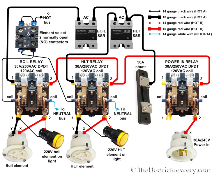
Looking at the wiring diagram (attached), it's a 220v circuit, but has a 110 outlet for the pumps. How can you have a 110 outlet connected on this circuit? Won't that either destroy the outlet or fry the pumps?

Also, these plans have it to where the HLT or the BK is on at any given time. I want to run both at the same time so I can do my mash water from the BK and the HERMS & Sparge water from the HLT. Will I be able to connect one 220v 30amp cord into this to run everything with a 60amp breaker?

Wiring Diagram.jpg
 
220V AC is two-phase - there are two hot lines running 110V* away from the neutral line, 180 degrees out of phase with each other (effectively one is +110V and one is -110V).

The heating element is connected between the two hot phases, so sees a voltage difference of 220V. The pumps are connected between one hot phase and neutral and so see a voltage difference of 110V to ground. You really need to understand this if you are thinking about modifying any control panel design. See the stickied primer at the top of the subforum.

If you want to run both element at the same time, you need all cords up to the control panel to be able to handle 50-60A (50A is OK, I think), as it will be carrying ~50A with both elements on. The cords from the control panel to each element can be 30A cords.

* technical detail - actually 110V is the root mean square of the voltage difference between the hot line and the neutral line - the actual voltage difference varies from -155 to +155 Volts in a sine wave. Similarly for 220V AC, where the two lines vary from -155 to +155 V to ground/neutral, with one being -155V when the other is +155V. I'll just say 110V and 220V for clarity.
 
This diagram shows you using SSRs to trigger mechanical relays.. what is the purpose here? Especially if you are using the PIDs to control electric elements, get the proper SSRs to directly fire the elements. You are going to wear out the mechanical relays with speed and frequency of controlling those elements.

Basically, the mechanical relays are both redundant, and an almost sure failure point.
 
220V AC is two-phase - there are two hot lines running 110V* away from the neutral line, 180 degrees out of phase with each other (effectively one is +110V and one is -110V).

technically, it is a single-phase system, not two-phase. there are two legs but not truly two phases. 'split-phase' is a more applicable term. and the legs are not 180 degrees out of phase. phase shift is an angular measurement between different phases in a multi-phase system and since this is single-phase, there is no phase shift. the legs are rather 180 degrees out of polarity with one another. if it was a true two-phase system 180 degrees out of phase, output voltage would be zero. ;)

This diagram shows you using SSRs to trigger mechanical relays.. what is the purpose here? Especially if you are using the PIDs to control electric elements, get the proper SSRs to directly fire the elements. You are going to wear out the mechanical relays with speed and frequency of controlling those elements.

Basically, the mechanical relays are both redundant, and an almost sure failure point.

the whole diagram is odd. the ssr elements are being fired with one leg, need red and black to each ssr. the mechanical contactors are for isolation, not switching by pid control.
 
the whole diagram is odd. the ssr elements are being fired with one leg, need red and black to each ssr. the mechanical contactors are for isolation, not switching by pid control.

Are we looking at the same diagram? Its correct.

As you stated the Contactors are for isolation.

Contactors are being controlled by the 3 way Switch in the bottom middle, you can see its wires going to the coil. The SSR's are being controlled by the PID as it should be.
All the SSR is doing is breaking one leg of the possible 220V going through the contactor, and because theres no neutral, its in essence killing all power to the element.
This is pretty much identical to Kal's schematic from TheElectricBrewery, you can ignore the shunt if you arent using an ESTOP.
elements.jpg
 
This diagram shows you using SSRs to trigger mechanical relays.. what is the purpose here? Especially if you are using the PIDs to control electric elements, get the proper SSRs to directly fire the elements. You are going to wear out the mechanical relays with speed and frequency of controlling those elements.

Basically, the mechanical relays are both redundant, and an almost sure failure point.

??? Look at the diagram, the mechanical contactor's are controlled by a 3 way toggle switch going to the coils.

As for OP's original question, what is your use case for using both BK/HLT together? Is it so you can do back to back batches? Or is it just so you can keep your HLT water warm while your sparging?

If its keeping the HLT warm while sparging into BK then you dont need that element to be firing, its fine if it cools off a bit while sparging temp isnt really mandatory at that point in the process and you can get away with just 30A of power. On the other hand if your wanting to mash in a new beer while your boiling your first, then you need a 50A box..which is the same thing you posted but you just need to buy beefier contactors/SSR's and use thicker wiring.

FWIW My build currently is based off the exact same diagram
https://www.homebrewtalk.com/showthread.php?t=539826
 
Pls be careful if you are not adept at electrical circuitry. This is serious power and can cause damage/fire/death if you don't adhere to standards and safety practices. You might be best served buying an off the shelf solution like Kal's or Electric Brewing Supply's panels. They will cost a bit more but will save you time and headaches plus will perfectly work and be safe.

-BD
 
Are we looking at the same diagram? Its correct.

As you stated the Contactors are for isolation.

Contactors are being controlled by the 3 way Switch in the bottom middle, you can see its wires going to the coil. The SSR's are being controlled by the PID as it should be.
All the SSR is doing is breaking one leg of the possible 220V going through the contactor, and because theres no neutral, its in essence killing all power to the element.
This is pretty much identical to Kal's schematic from TheElectricBrewery, you can ignore the shunt if you arent using an ESTOP.

bah, my bad. you are correct, not sure what i was looking at. :drunk:
 
This diagram shows you using SSRs to trigger mechanical relays.. what is the purpose here? Especially if you are using the PIDs to control electric elements, get the proper SSRs to directly fire the elements. You are going to wear out the mechanical relays with speed and frequency of controlling those elements.

Basically, the mechanical relays are both redundant, and an almost sure failure point.

You are wrong!

The SSR's are not triggering the contactors (relays). The contactors are "triggered" by an on-off-on toggle switch to the lower right of the contactors. When the contactors are not activated, no current can flow to the elements. The contactors plus toggle switch insure that only one element can be powered on at a time, or both elements can be forced off. The contactors are not redundant, they provide a required switching function, and extra safety by insuring no voltage is on an element unless the element is selected with the toggle switch. The contactors have very low on-off cycling rates, and are less likely to fail than the SSR's. The actual cycling of the elements is controlled by the SSR switching.

Brew on :mug:
 
technically, it is a single-phase system, not two-phase. there are two legs but not truly two phases. 'split-phase' is a more applicable term. and the legs are not 180 degrees out of phase. phase shift is an angular measurement between different phases in a multi-phase system and since this is single-phase, there is no phase shift. the legs are rather 180 degrees out of polarity with one another. if it was a true two-phase system 180 degrees out of phase, output voltage would be zero. ;)
Sorry, I can't see the distinction you are making.

Reversing the polarity for a sinusoidal voltage is identical to shifting it 180 degrees out of phase, as V sin(ωt) = - V sin(ωt+π). And the potential difference between two sinusoidal voltage signals 180 degrees out of phase is V sin(ωt) - V sin(ωt+π) = 2V sin(ωt).

Now, there may be some power engineering terminology that differs to this, but that's what's physically going on with the voltages.
 
technically, it is a single-phase system, not two-phase. there are two legs but not truly two phases. 'split-phase' is a more applicable term. and the legs are not 180 degrees out of phase. phase shift is an angular measurement between different phases in a multi-phase system and since this is single-phase, there is no phase shift. the legs are rather 180 degrees out of polarity with one another. if it was a true two-phase system 180 degrees out of phase, output voltage would be zero. ;)
Wrong! Hot 1 & Hot 2 are 180˚ out of phase with each other. When Hot 1 is at maximum w.r.t ground, Hot 2 is at minimum w.r.t ground, and vise versa. That is 180˚ out of phase.

the whole diagram is odd. the ssr elements are being fired with one leg, need red and black to each ssr. ...
Wrong! The red highlighted phrase is not just wrong, it is dangerous!

An SSR is just an electronic SPST switch. You don't connect Hot 1 & Hot 2 (or Hot/Neutral) with a SPST switch, as it just causes a short when the switch is closed.

Brew on :mug:
 
As for OP's original question, what is your use case for using both BK/HLT together? Is it so you can do back to back batches? Or is it just so you can keep your HLT water warm while your sparging?

From what he says in the OP, I think the use case is heating the strike water in the BK while heating the sparge water in the HLT/HERMS tank before mashing in.

I guess that's necessary if your HLT isn't big enough to hold and heat the strike water and sparge water at the same time, but for a three vessel system with equal sized vessels, it doesn't seem necessary. I've not used that kind of system, but I guess the HERMS coil has to mounted low enough in the HLT that it's mostly covered by the just the sparge water volume.
 
Sorry, I can't see the distinction you are making.

Reversing the polarity for a sinusoidal voltage is identical to shifting it 180 degrees out of phase, as V sin(ωt) = - V sin(ωt+π). And the potential difference between two sinusoidal voltage signals 180 degrees out of phase is V sin(ωt) - V sin(ωt+π) = 2V sin(ωt).

Now, there may be some power engineering terminology that differs to this, but that's what's physically going on with the voltages.

two-phase is a phrase that many have adopted to describe a 120/240V system but multi-phase systems have vector (angular) differences between the phases. since 120/240 is a single phase system, it can only have one 'phase'. it is split-phase, not two-phase.

true two-phase generation existed back in the day but quickly fell out of favor once three-phase came into being. true two-phase systems still exist today but in specialized applications like stepper motors.

http://www.3phasepower.org/2phasesystems.htm

now this is certainly a fine point that has, like, nothing to do with brewing beer, just an interesting factoid.:mug:
 
I missed the switches!!! It makes more sense now!

Are we looking at the same diagram? Its correct.

As you stated the Contactors are for isolation.

Contactors are being controlled by the 3 way Switch in the bottom middle, you can see its wires going to the coil. The SSR's are being controlled by the PID as it should be.
All the SSR is doing is breaking one leg of the possible 220V going through the contactor, and because theres no neutral, its in essence killing all power to the element.
This is pretty much identical to Kal's schematic from TheElectricBrewery, you can ignore the shunt if you arent using an ESTOP.
elements.jpg
 
From what he says in the OP, I think the use case is heating the strike water in the BK while heating the sparge water in the HLT/HERMS tank before mashing in.

I guess that's necessary if your HLT isn't big enough to hold and heat the strike water and sparge water at the same time, but for a three vessel system with equal sized vessels, it doesn't seem necessary. I've not used that kind of system, but I guess the HERMS coil has to mounted low enough in the HLT that it's mostly covered by the just the sparge water volume.

True, honestly i think it would be less work to just buy a bigger HLT than deal with the move from 30A->50A if thats the case. :mug:
 
Is anyone good at looking at a schematic for my control panel and helping me correct some issues for how it got wired by the previous electrician?
 
Is anyone good at looking at a schematic for my control panel and helping me correct some issues for how it got wired by the previous electrician?
I can probably help. But you should start at new thread for your questions, rather than add them on to this old (necro) thread.

Brew on :mug:
 

Latest posts

Back
Top