Brew Controller Build Questions

Homebrew Talk - Beer, Wine, Mead, & Cider Brewing Discussion Forum

Help Support Homebrew Talk - Beer, Wine, Mead, & Cider Brewing Discussion Forum:

This site may earn a commission from merchant affiliate links, including eBay, Amazon, and others.

BitterSweetBrews

Tim Trabold
Joined
Dec 9, 2014
Messages
453
Reaction score
103
Location
Omaha
OK, here is my system and what I want to do. I would appreciate some advice on feasibility and method.

I have always propane brewed but want to build an electric brewery because they are cool and it is getting cold outside. I have been collecting parts and working on preliminary tasks for a few months.

First my infrastructure. I am listing what I paid for stuff in case someone wants to total up what it will cost them ($300-$400, at least)

I have run a 240Volt, 30Amp, 4 wire circuit ($14 breaker) to a sub-panel in my future brewery (my workshop - 10Ga wire). The sub-panel is actually a Midwest Electric Spa Panel I got on ebay for about $34. I had the 10 gauge wire but it would have cost about $100 to purchase it. The panel came with a 240V/50Amp GFCI breaker and slots for 4 additional normal breakers (they are not protected by the GFCI breaker). I know that the 50amp GFCI breaker is more than the 30 Amp circuit I created - but I am using it for the GFCI. The breaker on the main panel will trip in an overload over the 30 amps it is wired for. I have added off of the sub-panel two 20 amp circuits, one on each leg of the 240 run from the main panel. On the 240v GFCI circuit I have a 30 Amp, 4 prong dryer outlet and an L6/30 Outlet. The brew controller will plug into one of these. On each of the 20 amp circuits ($8 for breakers) I have runs to a standard 20 Amp GFCI outlet ($10 ea) which is in front of an L5/20 outlet (I had a pull, but it would have cost about $11). I also have a previously installed 120V/20A GFCI circuit from the main panel in the same area that I could use if necessary.

Now my brewing Equipment. I have built most of this recently and haven't used it yet. So this is where some of my questions will come in.

I have a 50 liter keggle with a 5400 watt ULWD ripple element (Keg-$25, Element-$28). It will run at 240V. For now I plan on using it for heating strike and sparge water as well as a boil kettle.
I have a 54 quart cooler I use as a mash tun (had)
I have a SS RIMS tube with a 5400 ULWD fold over element and thermowell (about $60 in SS parts - $25-Element). It will run at 120V so as to not scorch the wort.
1 Chugger pump with SS head.($129)

Here are the parts I can use for my controller and about what I paid for them:
2 - MYPIN PD4 PIDs for RIMS and HLT (these are the model with manual control) $22 ea
1 - 9500W High Power SCR Electronic Volt Regulator Speed Controller Governor Dimmer for Boil Control $20 (I tested this by itself with the keggle and it works great).
2 - SSR-40DA 40A /250V W I/O 3-32VDC/24-380VAC & Heat Sink $8 ea
3 - MAGNECRAFT 92S7A22D-120A Relay,Power,6 Pin,DPST-NO,30A,120VAC $7 ea
4 - DPST Heavy Duty 20A Switches $2.25 ea
3 - DPDT Heavy Duty 20A Switches (ON-ON) $2.75 Ea
3 - DPDT Heavy Duty 20A Switches (ON-OFF-ON) $2.80 ea
1 - L5-20 120v outlet (I had it but they cost around $11)
1 - L6-30 240v outlet ($11)
1 - 120V/15A duplex outlet (I had it but they cost around $1)
3 - Thermocouples ($5 each)
3 - XLR Outlets and plugs ($10)
240V lights ($5)
Wiring panels ($8)
120V PC FAN (Free)
Misc. elect. - connectors, 10Ga cord, wire, etc. (maybe $20 total)

I plan on building a system based on the Instructable - "Electric Brewery Control Panel on the Cheap" by jmengel

I have some questions and I want to make some modifications. I would appreciate feedback.

1. Since I plan on using the keggle as both an HLT and boil kettle I am concerned with controlling these two functions. Is the manual mode on the MYPIN PIDs easy and quick enough to control and move temp up and down? I have the SCR controller/governor which works great to turn the burner up and down with the turn of a dial. I think using it may be quicker than the PID and lessen the chance of a boil-over while pushing buttons on the PID. What does anyone think about this? Is this an issue with PIDs?

2. If I were to put the SCR controller in the panel how and where in the circuit could I switch the element plug from PID to SCR? Can I just switch the element over from the PID?. Where can I insert the relay for this if I need one? Can I leave the PID on while running from the SCR Controller to use as a thermometer on the kettle without kicking the relays on. In other wordsm can I just turn PID control off and leave monitoring on?

3. Finally an important operational question, with both a 120v/5500 watt (1225 watt efective) RIMS circuit and a 240V/5500 watt HLT circuit, will I be able to run both of these elements at the same time? I could run a seperate cord for the RIMS to the previously installed 120V/20Amp circuit but I don't really want two cords coming out of my controller box and don't want to build a second one.

I would appreciate any advice.

Thanks.
Tim
 
1. Since I plan on using the keggle as both an HLT and boil kettle I am concerned with controlling these two functions. Is the manual mode on the MYPIN PIDs easy and quick enough to control and move temp up and down? I have the SCR controller/governor which works great to turn the burner up and down with the turn of a dial. I think using it may be quicker than the PID and lessen the chance of a boil-over while pushing buttons on the PID. What does anyone think about this? Is this an issue with PIDs?

I like the speed and simplicity of a knob for controlling my BK. I don't have any experience with the MYPIN PID, so I don't know how well the manual mode works.

2. If I were to put the SCR controller in the panel how and where in the circuit could I switch the element plug from PID to SCR? Can I just switch the element over from the PID?. Where can I insert the relay for this if I need one? Can I leave the PID on while running from the SCR Controller to use as a thermometer on the kettle without kicking the relays on. In other wordsm can I just turn PID control off and leave monitoring on?

You could switch the control signals from the SCR and PID back and forth to the SSR with a double pole double throw toggle switch.

The two SSR control terminals would be connected to the center contacts of the toggle switch.
The PID and SCR would be connected to the two outer contacts on opposing sides of the switch.


3. Finally an important operational question, with both a 120v/5500 watt (1225 watt efective) RIMS circuit and a 240V/5500 watt HLT circuit, will I be able to run both of these elements at the same time? I could run a seperate cord for the RIMS to the previously installed 120V/20Amp circuit but I don't really want two cords coming out of my controller box and don't want to build a second one.

These two elements operating at the same time will pull a little over 33 amps through one side of your 30 amp breaker.

You will need to up-size the circuit capacity for your brew panel or run the RIMS from a separate 120 volt circuit.
 
processhead,

Thanks for the input.

I like the speed and simplicity of a knob for controlling my BK. I don't have any experience with the MYPIN PID, so I don't know how well the manual mode works.

I agree. I have tested it and it is fast from knob turn to boil down. Almost as fast as turning off a propane burner.


You could switch the control signals from the SCR and PID back and forth to the SSR with a double pole double throw toggle switch.

The two SSR control terminals would be connected to the center contacts of the toggle switch.
The PID and SCR would be connected to the two outer contacts on opposing sides of the switch.

That's just the advice I needed. Once I am on the SCR I should be able to turn the PID control off. I have just been brain dead trying to think of where to put the switch. I have an extra On/Off/On switch that will work perfect.


These two elements operating at the same time will pull a little over 33 amps through one side of your 30 amp breaker.

You will need to up-size the circuit capacity for your brew panel or run the RIMS from a separate 120 volt circuit.

Yeah, I already figured that one out, once I remembered Ohms Law. It's sucks because I just finished remodeling the rest of my basement. I ran a conduit to my workshop for future use but it is too small for 8 or 6 gauge wire. On top of that, after I finished the basement I ran into a roll of 6 gauge romex I forgot I had. That would have been perfect.

Thanks, for your advice.

I see your from NE, me too, West Omaha / Elkhorn (not far from Upstream Brewing).
 
I see your from NE, me too, West Omaha / Elkhorn (not far from Upstream Brewing)
.

I'm in Gretna.

How long is your conduit run, and what size conduit did you use?
6-3 romex is pretty stiff, but only about 1/2" in diameter.

Loose conductors are also easier to pull, another option.
 
Manual mode on a PID works by setting the "duty cycle" which determines what percentage of the time the element is on as opposed to a potentiometer which reduces the current going to the element, but runs it 100% of the time. With most PID systems that I've seen, people tend to set them to around 60% cycle. You can play with the cycle length to figure out what works best for your system as the shape and size of your kettles will have some effect on how vigorous of a boil they can contain. In manual mode, the PID will ignore the data sent to it from the temp probe and cycle between off and on based on the set time intervals. In automatic mode, it will utilize the temp probe interface to determine when to fire the element and may keep the element on for longer or shorter periods of time to maintain the SV.

I would add an SSR so that you have one SSR on each leg of the element in the HLT. SSR's fail in an on or closed state. If you only run one leg on an SSR and it fails, your element will be stuck on. If you have the second SSR, you have a redundant control that adds a bit of safety and reliability to your system.
 
How long is your conduit run, and what size conduit did you use?
6-3 romex is pretty stiff, but only about 1/2" in diameter.

Loose conductors are also easier to pull, another option.

The run is about 40 feet. It is 1/2" flex. I checked the fill capacity using the calculator at "http://www.electrician2.com/calculators/rf_calculator.html". I can't run enough wires larger than 10 gauge. You are right, the larger wire is way to stiff to even try.

With the 30 amp 240v circuit, my only real choice is to just not run the hlt/boil kettle while using the RIMS. With an insulated mash tun that shouldn't be a big issue. I really don't want two power cords.

I guess another option, which I hadn't thought of until now, would be to run the HLT/Boil element at 120V, while the RIMs element is turned on. Since the sparge water amount would not be near the volume or heat of the full boil, the time during the mash should give it time to heat up. That might be a good solution. I would be able to keep the amperage below my circuit level and still be able to save some time doing two things at once.

FYI, I can sparge from a 5 gallon cooler but need to sparge from the HLT/Boil kettle and drain the wort into a 5 gallon bucket until the HLT/Boil kettle is empty.
 
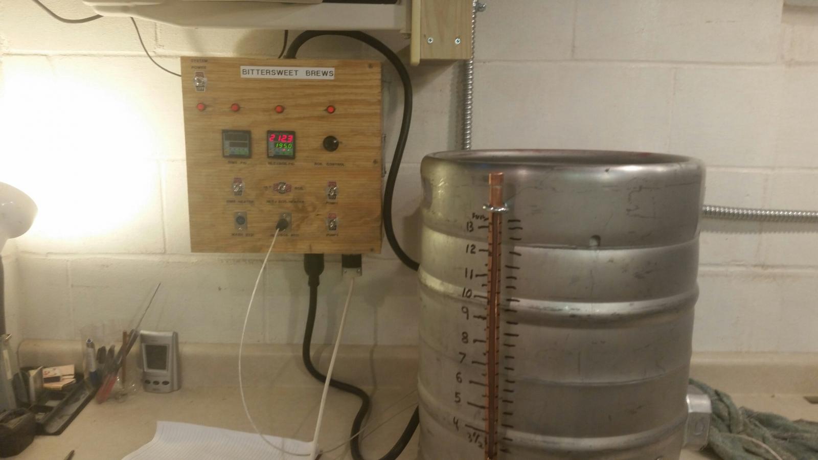
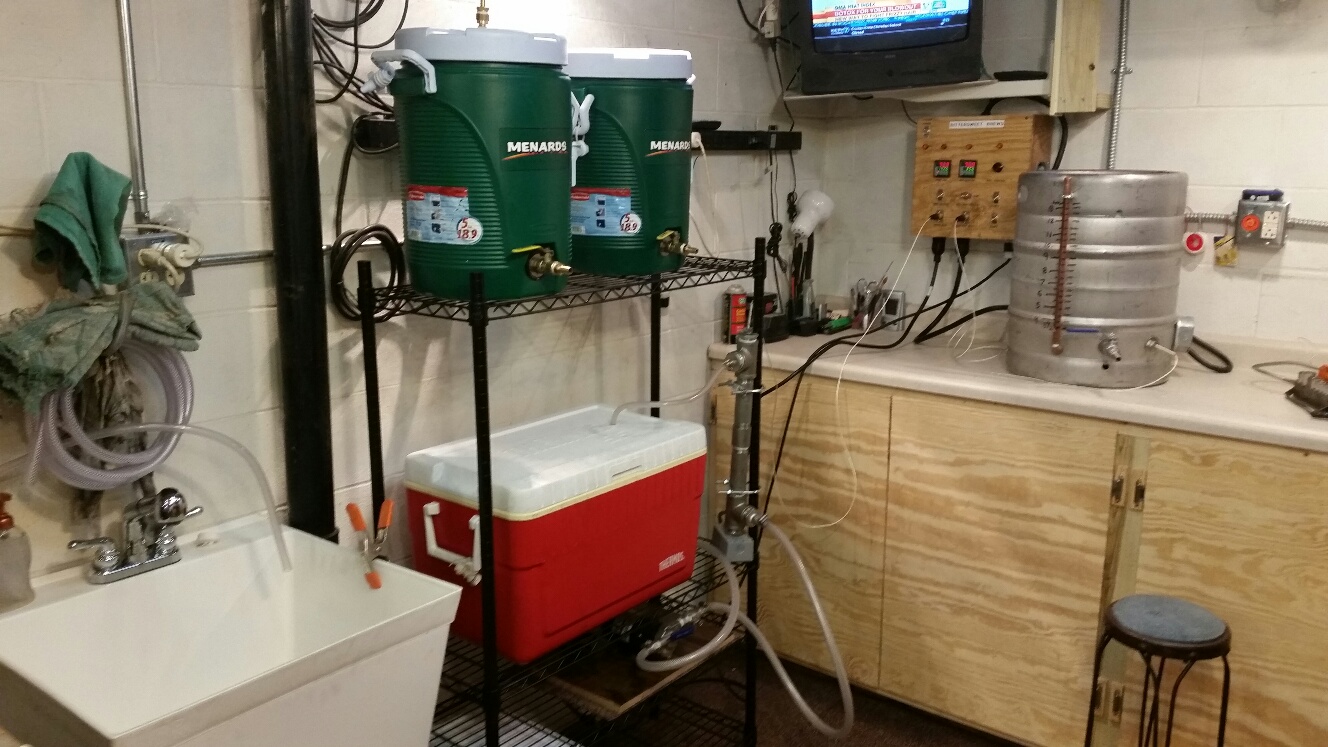
I have finished the build of my controller. I have run a bunch of tests and it works great! I plan on a brew christening this weekend.

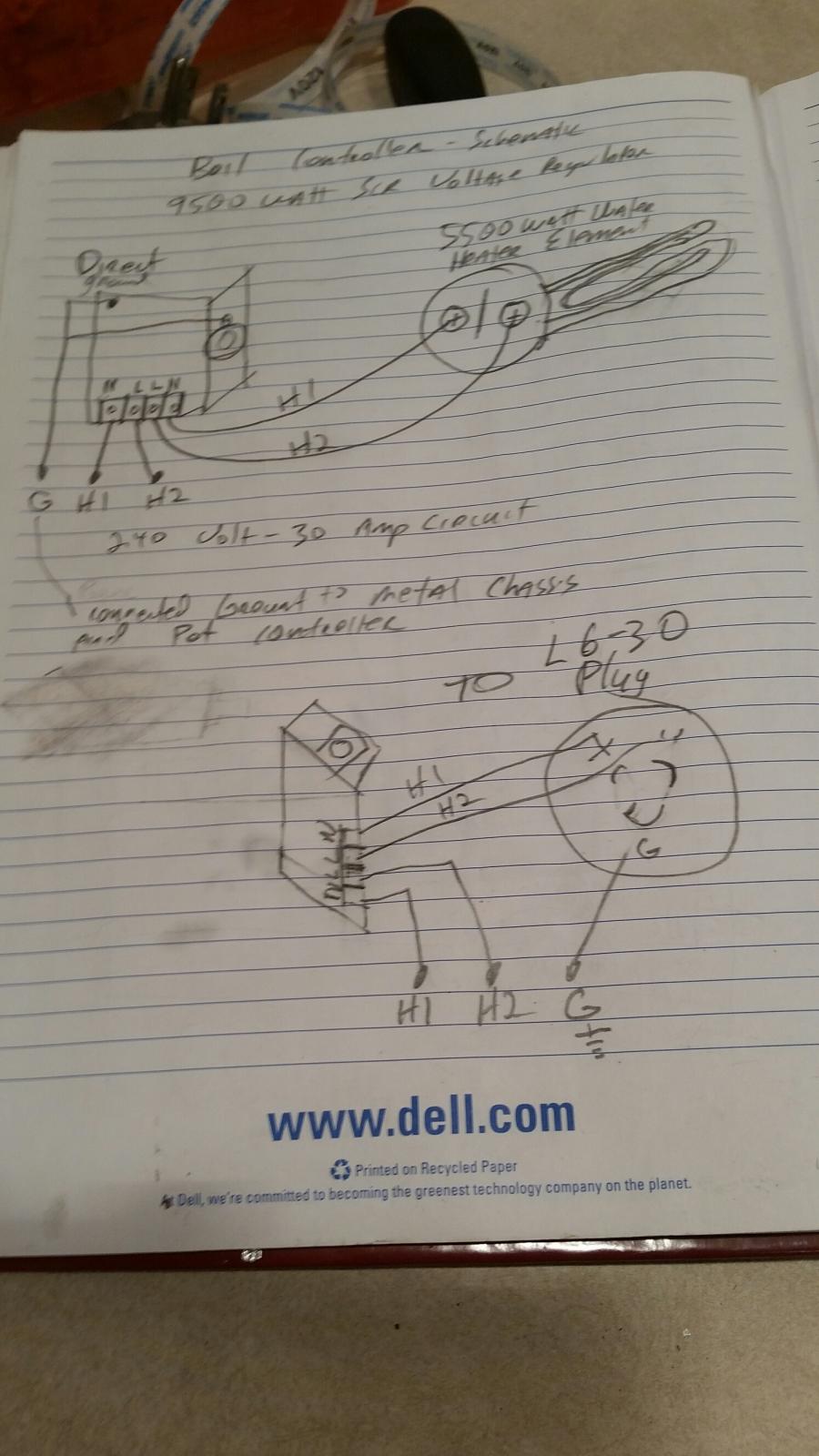
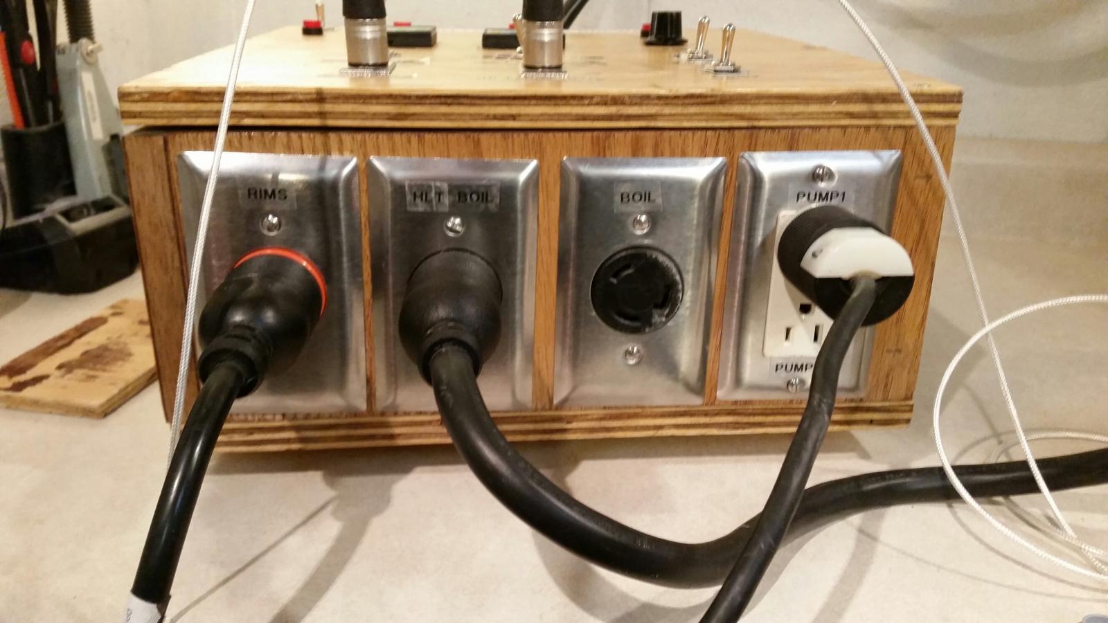
I ended up with a 120v RIMs PID circuit, a 120v/240v HLT PID circuit and a 240v SCR Boil Circuit. When the 120v/240V circuit (it has an L6-30 outlet) is switched to the HLT side, it runs at 120v and both it and the RIMS circuit can run. The kettle element is running at 120v/1375 watts. When it is switched to the Boil side, it disconnects and shuts down the 120V RIMS circuit and runs the kettle element at 240v/5500 watts. So, I can't overload my breaker. I only have a single HLT/Boil kettle so I will only be using one L6-30 outlet at a time. I do have two L6-30 outlets, one on the HLT/Boil PID and the other for the SCR control. They are currently separated. To use the SCR I have to unplug it from the HLT/Boil PID outlet and plug it into the SCR outlet. I can still use the HLT/Boil PID to monitor temp, but it isn't controlling anything. I have routed a switch recess in the back of the front bezel which I plan to use for a switch to control a cutoff relay to the SCR to element power connection (once I buy it and re-design the circuits).

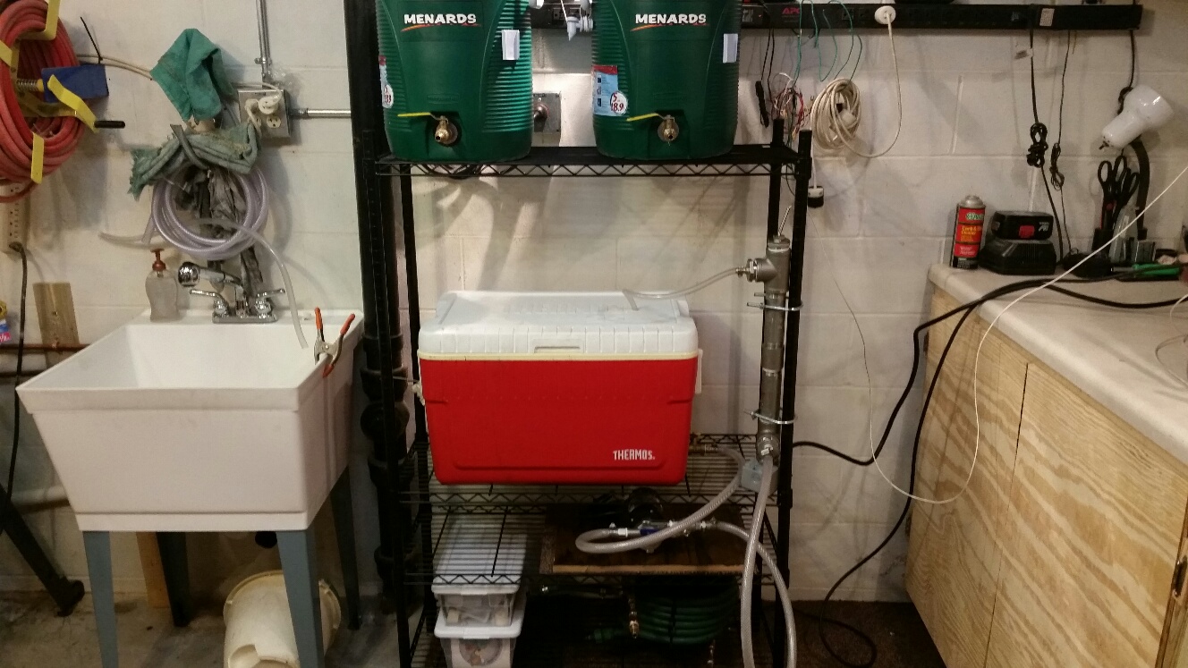
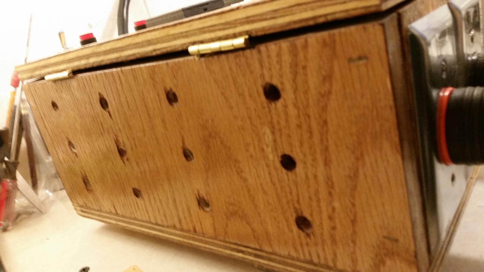
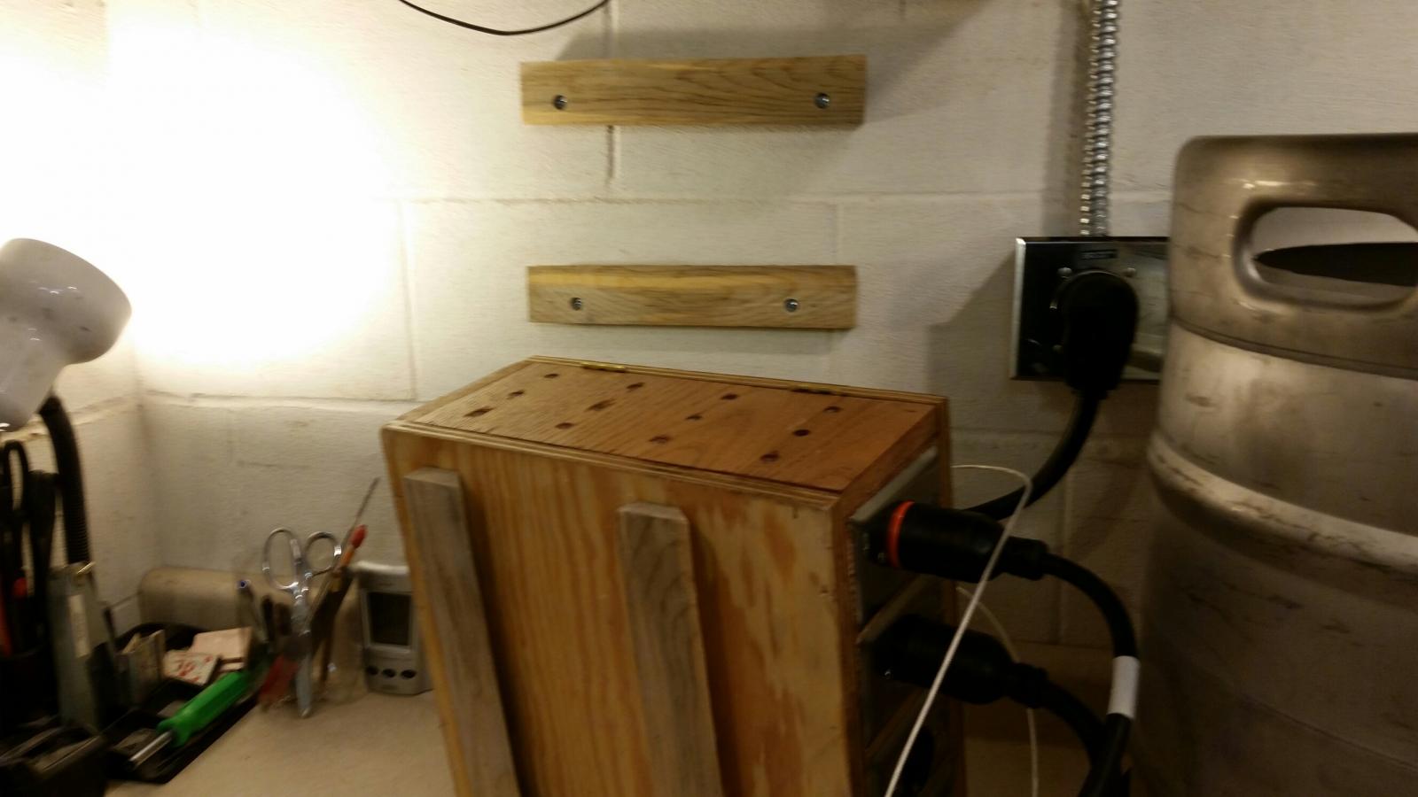
I am pleased with how it turned out. I uploaded a few pictures.

20141231_171607_resized_1.jpg


20141231_171616_resized_1.jpg


20141231_173812_resized_1.jpg


20150102_014602_resized_1.jpg


20150105_215204_resized_1.jpg


20150105_215232_resized.jpg


20150107_082138_resized_1.jpg


20150107_082230_resized_1.jpg


20150107_082233_resized.jpg


20150107_202522_resized.jpg
 
A heads up for anyone with a MYPIN PD4 controller.

Follow the wiring diagram on the controller itself, not the instruction sheet that came with it. At least compare the two.

While the instruction sheet is 99% correct, it had the polarity of the SSR output reversed. It wouldn't work at first. I troubleshot things and found the discrepancy in the diagrams. Once I wired based on the PID label, it worked properly. It is lucky I didn't blow my SSRs.

Also, I bought the two MyPIN PD4 controllers from two different sources. On one it is missing the connections for Alarm2. There are no screw panels where they should be. I don't need them so it doesn't matter for me. Just look out.

Otherwise, they work great so far.
 
I brewed twice last weekend to break in the system. I started with a Rogue Shakespeare Stout Clone on Saturday and then a Lienie Summer Shandy Clone on Sunday (for my wife). I am stoked with how well everything worked! I could not be happier with the controller. It did everything I expected.

After the Saturday brew I took some additional time learning how to work the PIDs and re-calibrated both of my temprature sensors. I boiled water, then set the offsets on the controllers to match their sensor. I had done this on one of them but not the other. It was a few degrees off.

It still took about 5-6 hours start to finish for both batches. The Stout took a little longer as I was figuring out methods. The Shandy went much faster as I continued to learn tricks for the system.

I created a whirlpool pipe out of some fittings and copper tubing which I used Sunday. I whirlpooled as it cooled channelling it through the counterflow chiller and back into the boil kettle. Then kept it going for a few more minutes before transferring into the fermenters. I might have gotten a little cleaner output, but time will tell on that.
 
The run is about 40 feet. It is 1/2" flex. I checked the fill capacity using the calculator at "http://www.electrician2.com/calculators/rf_calculator.html". I can't run enough wires larger than 10 gauge. You are right, the larger wire is way to stiff to even try.

With the 30 amp 240v circuit, my only real choice is to just not run the hlt/boil kettle while using the RIMS. With an insulated mash tun that shouldn't be a big issue. I really don't want two power cords.

I guess another option, which I hadn't thought of until now, would be to run the HLT/Boil element at 120V, while the RIMs element is turned on. Since the sparge water amount would not be near the volume or heat of the full boil, the time during the mash should give it time to heat up. That might be a good solution. I would be able to keep the amperage below my circuit level and still be able to save some time doing two things at once.

FYI, I can sparge from a 5 gallon cooler but need to sparge from the HLT/Boil kettle and drain the wort into a 5 gallon bucket until the HLT/Boil kettle is empty.
you have other choices...I use a 30a line to my setup with 2 4500w elements (which are MORE than enough for 5-10gallons) I also use a 1000w ULWD 240v cartridge heater inside my rims tube this allows me to have both the rims and hlt OR BK on at the same time and only draw about 25 amps with pumps on....
Also keep a close eye on the SCR unit... Many who have used them have reported they undersized some components like the traces on the board to the fuse and this burns up and fails..
 
A heads up for anyone with a MYPIN PD4 controller.

Follow the wiring diagram on the controller itself, not the instruction sheet that came with it. At least compare the two.

While the instruction sheet is 99% correct, it had the polarity of the SSR output reversed. It wouldn't work at first. I troubleshot things and found the discrepancy in the diagrams. Once I wired based on the PID label, it worked properly. It is lucky I didn't blow my SSRs.

Also, I bought the two MyPIN PD4 controllers from two different sources. On one it is missing the connections for Alarm2. There are no screw panels where they should be. I don't need them so it doesn't matter for me. Just look out.

Otherwise, they work great so far.
you do mean "TD4" right? thats what I use and I have never seen or heard of a PD4 model...

The reason you have no screw terminals for alarm 2 is likely because you have different models..the "td4-SNR" has two alarms while the "td4-ssr" only has one... careful when buying because there are other td4 models that wont even work to drive ssrs...
 
Great setup, thanks for posting your build. I'm embarking on a similar journey, which will likely end up in an unfinished basement.

Looking forward to your exhaust option, right now I'm looking at larger hoods vented out one of those small 1'x2' basement windows, or making a custom hood (likely out of wood and stained+sealed).

Another challenge is water+drain. It will go right near my main drain stack in the unfinished basement, but you can't just cut right into it and shove a pipe in there :) copper Hot/Cold water lines are right above and easy to T off from with PEX. Drain+Exhaust, build control panel, then wire up some probes+elements.

Cheers! :mug:
 
you do mean "TD4" right? thats what I use and I have never seen or heard of a PD4 model...

The reason you have no screw terminals for alarm 2 is likely because you have different models..the "td4-SNR" has two alarms while the "td4-ssr" only has one... careful when buying because there are other td4 models that wont even work to drive ssrs...


Yes I did mean TD4.

That's interesting about the differing models and the alarms. I thought both of mine were TD4-SNR's. I must have gotten a TD4-SSR without realizing it. No big deal, I don't really need two alarms anyway. But I was wondering why the terminals were missing for alarm 2.
 
Great setup, thanks for posting your build. I'm embarking on a similar journey, which will likely end up in an unfinished basement.

Looking forward to your exhaust option, right now I'm looking at larger hoods vented out one of those small 1'x2' basement windows, or making a custom hood (likely out of wood and stained+sealed).

Another challenge is water+drain. It will go right near my main drain stack in the unfinished basement, but you can't just cut right into it and shove a pipe in there :) copper Hot/Cold water lines are right above and easy to T off from with PEX. Drain+Exhaust, build control panel, then wire up some probes+elements.

Cheers! :mug:


I am thinking similarly about the exhaust options. I have the brewery placed under and to the left of a standard small basement window (about 15" x 30"). I take the window out and put a box fan in it and it does OK, but I need a better solution. I was thinking about maybe a concrete form, cut in half and then sealed and painted (if I can get one with a large enough diameter). I have also seen a few people using Formica or bathroom paneling with house-siding J-channels at the bottom to channel the drips.

My workshop/brewery are in an un-finished part of my basement, so I was able to tie into some water pipes going to a bathroom upstairs. My sink is right next to a stack, but the level I would need to tie in is below the PVC and in the Cast Iron area. So, I ran a PVC pipe along the wall, around a corner and to a floor drain that my Air Conditioner and Water Softener already drain in. It is pretty much out of the way and not in a traffic area. I have framed a future bathroom in the finished part of the basement, but haven't gotten a plumber to bust the floor for the drains. When I get around to that, I'll have them do the sink too.
 
Yes I did mean TD4.

That's interesting about the differing models and the alarms. I thought both of mine were TD4-SNR's. I must have gotten a TD4-SSR without realizing it. No big deal, I don't really need two alarms anyway. But I was wondering why the terminals were missing for alarm 2.
I use the two alarm one myself for my rims... If the temp goes either above my high setpoint or drops below my min setpoint the alarm goes off and notifys me that some things wrong.. I use the single alarm pics for hlt and bk
 
I have brewed using the controller 6 or 7 times now. Still works great. I did make one modification worth noting.

I initially wired it so that if I had flipped the HLT/Boil switch to boil at 240v, it would shut off the 120v RIMs side & PID. I found that this was too limiting.

Based on an earlier reply/idea in this thread on ways to keep under my 30 amp circuit limits, I built a 240v / 4500w heat stick to use in a separate HLT. That way I don't have to use my 5500w boil keggle as an HLT. I have my first boil kettle, a turkey fryer I converted, that I can use for this. Also, I liked having the other RIMS PID available for temp monitoring, even if I am not using the RIMS at the time. Finally, I may want to try doing HERMs with my old immersion wort chiller and being able to monitor mash temp and water temp would be a must.

Anyway, I just moved the PID power to the middle of the HLT/Boil - on/off/on switch, so it is always on.
 
This may have been answered but I can't find it. What Temperature Probes did you use and where did you get them? I'm building this now and already ordered most of the parts.
 
I mainly use PT100 temperature sensors. I have also used K type thermocouples. The PT100s are more sensitive and react faster. PT100s cost a little more, but not much. I have usually purchased them on E-bay. You can find ones with 1/2" threads that will go right into a standard weld-less fitting.

With either one you do have to calibrate it to find out its differential to put in the PID. I put them in freezing water and boiling water. I then label the cables with the differential on paper covered in tape. You need to know how many degrees to scale the PID up or down from boiling/freezing so it shows an accurate temperature when it is boiling or at lower temps. Every sensor is different.

To calibrate you plug/wire the probe into the PID and put it in boiling water. Then based on the temp water boils in your area (based on elevation) set the differential on the PID to add or subtract degrees from the readout until it shows the correct temperature.

I have a switch on my portable 120v controller that lets me choose either a PT100 or K type probe. I then set the PID to which ever one I am using and alter the differential to compensate. It then shows accurate temps on the readout. I put the probes on an XLR plug so I can unplug them from the controller when not in use.
 
I brewed twice last weekend to break in the system. I started with a Rogue Shakespeare Stout Clone on Saturday and then a Lienie Summer Shandy Clone on Sunday (for my wife). I am stoked with how well everything worked! I could not be happier with the controller. It did everything I expected.


Do you have those recipes handy? My wife loves the summer shandy and I'm a rogue guy!
 
Back
Top