3 wire 240 outlet to spa panel wiring question

Homebrew Talk - Beer, Wine, Mead, & Cider Brewing Discussion Forum

Help Support Homebrew Talk - Beer, Wine, Mead, & Cider Brewing Discussion Forum:

This site may earn a commission from merchant affiliate links, including eBay, Amazon, and others.

Twang

Well-Known Member
Joined
Jan 29, 2009
Messages
193
Reaction score
3
I want to run an extension cord to a spa panel for my Brew Boss controller.

From Brew-Boss:
"The power cable from the controller has three (3) wires, Black, White, and Green. The White and Black wires get wired to the HOT prongs of your plug (L1 and L2). The GREEN wire gets wired to the GROUND prong of your power plug. If you have a 4-wire receptacle, simply do not use the 4th prong, which is the Neutral wire."

My dryer outlet appears to only be 3 wire.
IMG_6427.jpg


How should I wire the spa panel? I am using PJs diagram as a guide
power-panel-6.jpg


Do I wire the bare copper wire where the yellow wire in the diagram indicates, with the exception of the yellow wire from the 50a GFCI to output?
 
I want to run an extension cord to a spa panel for my Brew Boss controller.

From Brew-Boss:
"The power cable from the controller has three (3) wires, Black, White, and Green. The White and Black wires get wired to the HOT prongs of your plug (L1 and L2). The GREEN wire gets wired to the GROUND prong of your power plug. If you have a 4-wire receptacle, simply do not use the 4th prong, which is the Neutral wire."

My dryer outlet appears to only be 3 wire.
IMG_6427.jpg


How should I wire the spa panel? I am using PJs diagram as a guide
power-panel-6.jpg


Do I wire the bare copper wire where the yellow wire in the diagram indicates, with the exception of the yellow wire from the 50a GFCI to output?
how many amps does your controller draw?? that wiringin your outlet pic is either 14 or 12g so your looking at 15-20A tops depending on which.....
 
Not sure of the exact amps. It powers a 5500 watt element and the control box. Pump is on a separate 120v outlet. The breaker for the dryer outlet is 30a... would they really have run smaller wire than 10g?
 
Not sure of the exact amps. It powers a 5500 watt element and the control box. Pump is on a separate 120v outlet. The breaker for the dryer outlet is 30a... would they really have run smaller wire than 10g?

well the wiring in that picture apears to be regular 120v romex wire.... from that pic I would say its 14 or 12... and yes that would be too smal for sure. I could be wrong though best to check the wire at the other end in the panel.
people do all sorts of incorrect things when doing home imrovements who knows who put this line in and when do you?
 
Control box draws 25 amps... I wasn't expecting the outlet to be wired with 12 or 14g. Back to the drawing board I guess. I'm thinking my best option to hire an electrician to run a new outlet to where I brew in the garage, or rewire the existing dryer outlet and then make an extension cord as planned. ugh... :mad:
 
Is there any writing on the dryer outlet wiring? Seems odd that it would be 15 amp wire, that certainly isn't a 15 amp plug... I guess it don't matter as far as wiring your panel goes though.
 
Full_Size_Render_1.jpg

Full_Size_Render.jpg


I believe it is 10g after all. I wasn't able to pull any slack to view any writing on the wire jacket. But I took a snip off one of the wires. It just barely fits in the 10g slot on my strippers, too big for 12g.

So assuming this is 10g, how should I go about wiring the 3 wires to the spa panel and then to the brew-boss controller?
 
Did your spa panel come with instructions? Or is it identical to PJ's?


The power out from the breaker would just have 1 less wire (no neutral).
 
I plan on getting the same model PJ used for his diagram. I guess I am confused on the neutral and ground wiring.
 
Did your spa panel come with instructions? Or is it identical to PJ's?


The power out from the breaker would just have 1 less wire (no neutral).

Oops didnt see the second part of your post before my previous reply.
So the wiring will be the same as in the diagram except for the yellow wire going from the gfci to the output wont be there. right?
 
Great. Thanks for the help. I obviously don't know much about wiring but I can follow directions.
 
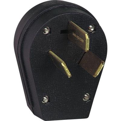
Probably a silly question but my dryer outlet has one of the blade inlets at 90 degrees.
IMG_6361.jpg


Do I have to use a plug with a 90 degree blade or can I use one with all angled straight blades like this:
b841edb6-84ce-420b-a75b-0c5df8cd093f_400.jpg
 
Full_Size_Render_1.jpg

Full_Size_Render.jpg


I believe it is 10g after all. I wasn't able to pull any slack to view any writing on the wire jacket. But I took a snip off one of the wires. It just barely fits in the 10g slot on my strippers, too big for 12g.

So assuming this is 10g, how should I go about wiring the 3 wires to the spa panel and then to the brew-boss controller?

That's very good news! I thought for sure from That pic that it was smaller wire, but pictures can be deceiving.
 
Probably a silly question but my dryer outlet has one of the blade inlets at 90 degrees.
IMG_6361.jpg


Do I have to use a plug with a 90 degree blade or can I use one with all angled straight blades like this:
b841edb6-84ce-420b-a75b-0c5df8cd093f_400.jpg

The L shaped blade is for 30 amps for a dryer, and the straight blade is for 50 amps for an electric range. I am not an electrician. I just had to buy a cord for a range, when I had a cord for a dryer hanging in my garage.

My understanding is that you shouldn't use an outlet and plug that would allow draw of more power than your wiring can safely handle. I don't think that 10 gauge wire would do well if 50 amps were pulled through it.
 
Im doing the same thing now.My plan is running a 3 wire dryer plug from spa panel that Ill plug into dryer outlet on brew day.coming out of spa panel is 25 ft 3 wire 10G extention cord to control box so I can brew upstairs or outside and not in my basement.Home depot or Lowes has the plugs you need..The plug I found at lowes was a 50amp with the L shape prong in the box to convert to 30 amp.
 
Not an electrian but older dryer outlets are H-H-N. The L shaped plug is a neutral and should use an insulated (white) wire, but it looks like you have 10/2 romex going to your dryer outlet and have a bare ground wire being used for the neutral. I think you really need to change the wiring and the outlet to 10/3 romex (4 wires) going to a 14-30r receptacle to go forward with your plan.

You'd run all four wires to the spa panel but only the H-H-G going out to your controller since it doesn't use the neutral. Since the spa panel will be a plug-in GFCI, you could run the power out from it directly to your controller if you wanted to save on another outlet and plug for that.

Obviously, you'll then need to swap your dryer plug out to a four wire plug (14-30p) as well.

I'd recommend having an electrician look at the dryer breaker and wiring since its looks wrong. No telling what else could be going on there.
 
not an electrian but older dryer outlets are h-h-n. The l shaped plug is a neutral and should use an insulated (white) wire, but it looks like you have 10/2 romex going to your dryer outlet and have a bare ground wire being used for the neutral. I think you really need to change the wiring and the outlet to 10/3 romex (4 wires) going to a 14-30r receptacle to go forward with your plan.

You'd run all four wires to the spa panel but only the h-h-g going out to your controller since it doesn't use the neutral. Since the spa panel will be a plug-in gfci, you could run the power out from it directly to your controller if you wanted to save on another outlet and plug for that.

Obviously, you'll then need to swap your dryer plug out to a four wire plug (14-30p) as well.

I'd recommend having an electrician look at the dryer breaker and wiring since its looks wrong. No telling what else could be going on there.

+1
 
Not an electrian but older dryer outlets are H-H-N. The L shaped plug is a neutral and should use an insulated (white) wire, but it looks like you have 10/2 romex going to your dryer outlet and have a bare ground wire being used for the neutral. I think you really need to change the wiring and the outlet to 10/3 romex (4 wires) going to a 14-30r receptacle to go forward with your plan.

I'd recommend having an electrician look at the dryer breaker and wiring since its looks wrong. No telling what else could be going on there.

Is this still a concern if I will only be using the dryer outlet for running an extension cord to the spa panel for my brew controller which doesn't use a neutral?
 
I would think that neutral is just a ground wire. Worst case is your gfci breaker trips and you have to move the neutral wire to the ground bar in your box (something that could be easily done anyways, though not sure how this would affect the dryer).
 
I would think that neutral is just a ground wire. Worst case is your gfci breaker trips and you have to move the neutral wire to the ground bar in your box (something that could be easily done anyways, though not sure how this would affect the dryer).

I have a gas dryer so this outlet isn't being used for anything. Since the neutral and ground bus bars are bonded in the main panel and since the brew control wont be using a neutral, it shouldn't matter if if its an insulated neutral or bare ground wire on the dryer outlet.... if I understand correctly...
 
I have a gas dryer so this outlet isn't being used for anything. Since the neutral and ground bus bars are bonded in the main panel and since the brew control wont be using a neutral, it shouldn't matter if if its an insulated neutral or bare ground wire on the dryer outlet.... if I understand correctly...

Well, you're still supposed to bring a neutral to the spa panel's neutral bar (the yellow line in PJ's diagram). It uses it for the electronics I believe. I'm not sure if using the bare ground will cause any tripping problems or not, but I still wouldn't do it that way personally. Maybe someone else will chime in.
 
Im wiring up my spa panel tomorrow and reading directions now.As I see it and what Ill be doing seems super easy. Going by pic your in first post:

output wires stay the same,eliminate_neutral- there is none
outlet: 2 hots stay the same (red blue in pic) eliminate neutral,mount ground from wire to ground bar
eliminate neutral between bus bars.
 
I found the easiest way to go about the setup was to buy a 3 wire dryer cord.Hook it up to spa panel as posted above and plug into dryer outlet. Run an extention cord out of spa panel at a length that works for where Im brewing.Hook up a 30Amp plug on the end of extention cord...done

We'll see cause its all getting done tomorrow.:ban:

Just make sure the output cord exiting the spa panel terminates with a female (receptacle) end. You don't want live male plug ends, if you value your safety. :)
 
I guess I am confused on the neutral and ground wiring.

You aren't the first one. This can be a very confusing subject. There are essentially three ways that a 240 V outlet is wired:
1)HHG: Two phases and ground. This is fine for loads that only use 240V and appears to be what you have. The only possible confusion WRT your photo is that the phase wires are black and white (I assume the ground wire is bare). Only neutral (grounded - not ground) conductors should be white.
2)HHN: There was for a time an exception in the NEC that allowed clothes dryers and ranges that had 120V components to use the neutral as the ground. This was premised on the idea that the 120V loads were small such that the current imbalance was small enough that cabinets tied to N wouldn't be more than a volt or two above ground. This is no longer permitted.
3)HHNG: All four wires.

The manufacturers of the Brew Boss neatly skirt all these issues by having the heaters powered from 240V and the 120V equipment (pumps) powered by a separate 120V circuit. It does not require, in the 240V connection, a neutral. The neutral is needed for the 120V parts of the system and is provided by a separate 120V plug. Just do what the instructions say. Wire a plug for the two hots and ground. If you use a 4 prong plug don't wire the neutral.

If you want to put a GFCI breaker in the panel go ahead. You don't have to connect the white wire since this circuit doesn't use neutral but it will be a neater installation if you do. Or put a wire nut on it.

Now if you want to use a subpanel from which you derive both the 120 and 240 volt circuits you will need to pull 4 wires from the main panel (including a neutral).

Do I wire the bare copper wire where the yellow wire in the diagram indicates, with the exception of the yellow wire from the 50a GFCI to output?

If you want to use a sub panel for just the 240 then essentially yes. Do not connect the GFCI white wire and connect the green or bare wire from the feed to the ground bus at the right of the box. Do not run a neutral wire to the load. The ground (bare) wire should be connected only to the ground bar on the right side of the box in the picture and that bar should be bonded to the box.
 
Those HHN circuits were only allowed when wired directly to the main service panel. That's why mobile homes have always used 4-wire outlets for dryers; their main service disconnect is out on the pole. So the 3rd wire is connected to BOTH the ground bar and the neutral bar because they are both tied together in the breaker box. (this assumes it was installed correctly) You can safely use it for a neutral connection OR a ground -- but you shouldn't use it for both (actual electric dryers exempted.)

Another way to derive a small 120V from a pure 240V for a light or timer or something is with a transformer. I have no idea what a little 1 to 2 amp transformer would cost, (and an inline fuse) but probably not much.
 
Has anyone got a 240v GFCI to work properly when wired HHG? There's a lot of confusion here and at the Mike Holt forums. It is clear that when wired for 240v you do not need a neutral on the load side (see wiring diagram on p11 from Square-D link below). The manufacturers state that you need neutral on the line side for the GFCI's "test" button to work (see both links). It's not clear to me if the GFCI will function without the "test" button, but without it you have no way to know. It's also not clear if the GFCI "test" button would work if you tied the ground wire to the neutral bus in your spa panel. If it does you'd be using an uninsulated ground wire as the neutral. Even if it does, it's certainly not to code, and I wouldn't do it.

From Siemens: "Note: A load neutral is not required on the circuit. However, the white line neutral (pigtail) must be connected to the panel neutral for the device to function."

From Square D (p11) "The 60 A QO260GFI and QOB260GFI GFCIs are limited for use on 208 Vac and 240 Vac two-wire systems. These GFCIs require the panel neutral connection to provide the 120 Vac power necessary for testing the ground-fault circuitry."
 
Has anyone got a 240v GFCI to work properly when wired HHG?

Yes, I have them in my panel and have connected 220V pump motors and and arc welders (both HHG). They don't trip the GFCI.

There's a lot of confusion here and at the Mike Holt forums. It is clear that when wired for 240v you do not need a neutral on the load side (see wiring diagram on p11 from Square-D link below). The manufacturers state that you need neutral on the line side for the GFCI's "test" button to work (see both links).

The test button works by returning some current from one of the load side H terminals through a path other than the other load side H or N terminal. It can connect either load side H to either the opposite line side H or N. Apparently they have chosen to connect to N. OP could connect the breaker's white wire to the feed G in order to have the test button work. It is only connected to G when the test button is pushed and as such, I suppose, might not constitute a code violation as long as the breaker's N terminal is not connected to anything. Or he could wicker his own test button in which a resistor is connected between load side H to G through the button contacts.


It's not clear to me if the GFCI will function without the "test" button,..
Only reason it wouldn't would be because of device failure which is what the test button is there to detect.

... but without it you have no way to know.
Just so.

It's also not clear if the GFCI "test" button would work if you tied the ground wire to the neutral bus in your spa panel.
That would depend on whether you bond it on the line or load side. If you do it on the line side then it should work. Imbalance (0-sequence) current flows back through the core except in the case of a fault to ground in which some of it doesn't. OTOH if you were to bond on the load side any imbalance current would return partly through the ground wire.

If it does you'd be using an uninsulated ground wire as the neutral. Even if it does, it's certainly not to code, and I wouldn't do it.

The main reason for not wanting to go there is that it has been known to cause serious overheating of some participants in this forum.

From Siemens[/URL]: "Note: A load neutral is not required on the circuit. However, the white line neutral (pigtail) must be connected to the panel neutral for the device to function."
Should say test device I would think unless they have something in there that won't allow the thing to function unless it senses 120 between 1 or both phases and the neutral and I can't think what advantage there would be to that. More modern GFCI's now launch a 120Hz test signal and expect it to be completely returned through the load terminals. This is, I think, to detect faults between like phases of separate circuits. Maybe it has something to do with that.
 
Those HHN circuits were only allowed when wired directly to the main service panel. That's why mobile homes have always used 4-wire outlets for dryers; their main service disconnect is out on the pole. So the 3rd wire is connected to BOTH the ground bar and the neutral bar because they are both tied together in the breaker box. (this assumes it was installed correctly)
The neutral and ground should only be bonded at the 'service entrance' and no where else. If the service entrance is on a pole then that is the only place neutral and ground should be bonded. Both must be run from the service entrance to any panel but they must be kept separate there and the panel must be bonded to the ground - not the neutral. Even electricians don't understand this. When my garage/brewery was built the service entrance for the house was moved to a box on the outside of the house and three panels in the house and garage fed through breakers from there. The electrician bonded neutral to panel and took that bond as the source of ground within the garage. The inspector said 'No, no' and made him tear out dry wall to run the proper ground conductors (from the rods at the service entrance) and separate them at the panel. This is why I am sensitive to this issue.

You can safely use it for a neutral connection OR a ground -- but you shouldn't use it for both (actual electric dryers exempted.)
Don't follow this. There must be a separate grounding system conductor and neutral. They can, and must be, joined only at the service entrance or at the source of a separately derived system (coming up).

Another way to derive a small 120V from a pure 240V for a light or timer or something is with a transformer.
This is the only legit way that I know of (other than an M/G set) to derive 4 wires from HHG. Were OP to use a transformer for 120 he would have to join one side of the transformer (or the center tap if he got a 120/0/120 transformer) to the main source G wire which would still be bonded to the box. He can then, because this is a separately derived system, tie the neutral of this separate system to that bond.


I have no idea what a little 1 to 2 amp transformer would cost, (and an inline fuse) but probably not much.

You'd be surprised (and not pleasantly). But all of this is moot as the Brew Boss has solved this problem by getting 120 (and its neutral) from a separate circuit.
 
Originally Posted by z-bob View Post
Those HHN circuits were only allowed when wired directly to the main service panel. That's why mobile homes have always used 4-wire outlets for dryers; their main service disconnect is out on the pole. So the 3rd wire is connected to BOTH the ground bar and the neutral bar because they are both tied together in the breaker box. (this assumes it was installed correctly)
The neutral and ground should only be bonded at the 'service entrance' and no where else. If the service entrance is on a pole then that is the only place neutral and ground should be bonded. Both must be run from the service entrance to any panel but they must be kept separate there and the panel must be bonded to the ground - not the neutral.

We're saying the same thing. If you have a properly-installed HHN dryer or range receptacle, it must originate in the service entrance panel, the single point where the ground and the neutral are connected. That's why you've never been able to have a 3-wire dryer cord in a mobile home; they are bonded at the meter instead of the breaker box, and there are 4 wires coming in.

I'm not an electrician, so I might be using the terminology a little wrong. I purposely did not say "service entrance panel" in my post because I didn't think anyone except the electricians would know the significance of that word. (don't get be started about grounded vs grounding conductors) :p
 
We're saying the same thing.
I think the intent is the same.

If you have a properly-installed HHN dryer or range receptacle, it must originate in the service entrance panel, the single point where the ground and the neutral are connected.
If the grounded conductor is uninsulated the cable must be type SE and must connect at the service entrance. Otherwise there is no restriction as to where the circuit can be sourced. But this is for existing wiring only. All current wiring must be done with G and N present.


That's why you've never been able to have a 3-wire dryer cord in a mobile home; they are bonded at the meter instead of the breaker box, and there are 4 wires coming in.
There is a separate paragraph (550.16) that says that no appliance frame may be connected to the grounded conductor (neutral). IOW the exception that used to apply in homes never applied in mobile homes/RV's/campers...
 
If you want to use a sub panel for just the 240 then essentially yes. Do not connect the GFCI white wire and connect the green or bare wire from the feed to the ground bus at the right of the box. Do not run a neutral wire to the load. The ground (bare) wire should be connected only to the ground bar on the right side of the box in the picture and that bar should be bonded to the box.

Just to double check, this is how I should wire the spa panel? No neutral in or out. Do not connect curly GFCI neutral wire to bar (put a wire nut on it?). And the GFCI will still work for safety purposes? (Excuse the Paint hack-job)

Keeping in mind there is a separate 120 feeding the brew boss controller for pump and lights/etc.

power_panel_6v2.jpg
 
I would be tempted to put the white pigtail lead on the ground bar. I would at least try it; it will either give you a working TEST button, or cause the GFCI to trip immediately. (I'm betting on the TEST button)
 
Just to double check, this is how I should wire the spa panel? No neutral in or out. Do not connect curly GFCI neutral wire to bar (put a wire nut on it?). And the GFCI will still work for safety purposes? (Excuse the Paint hack-job)
Yes, that should be fine if the breaker is the conventional sort of GFCI breaker and if the test circuit is between the two hots. If it isn't, (i.e. between one H and neutral) then the test button won't work. In this case connect the white wire to the ground bar (at the right) and try it again. This should make it work. You will only be connecting supply conductors to ground when you make the test (for a few milliseconds) so while this may be a letter of the code violation it certainly isn't one in spirit.
 
I called Eaton the manufacturer of my box to get a definitive answer,This is what I was told by the tech dept.

The GFCI portion of the breaker runs off of 120v (The neutral)If you do not have 120 coming into the box the GFCI WILL NOT WORK. He said "if" the neutral is tied in with the ground in the breaker panel that would give you 120. you can then disconnect the white neutral prewired to the neutral bar and connect it to the ground bar. And it "may" work.Test by pushing test button.THEY DO NOT RECOMMEND THIS METHOD.

edit-IF THE GROUND IS JUST A GROUND= NO GFCI
 
This is what I was told by the tech dept.

The GFCI portion of the breaker runs off of 120v (The neutral)If you do not have 120 coming into the box the GFCI WILL NOT WORK.
What this means is that the faults are sensed electronically and that the breaker is launching the 120 Hz signal I referred to in an earlier post. The chip (LM1851 or something similar) is powered by a bridge rectifier (whose pulses also supply the 120 Hz signal) and that DC is also used to trip the breaker (by triggering an SCR when the chip detects imbalance). Connecting the N wire to earth will provide the necessary source for the electronics but it does violate code as the current necessary to operate the circuitry, though small, would be drawn through the ground wire which is not supposed to be used for that role.

He said "if" the neutral is tied in with the ground in the breaker panel that would give you 120. you can then disconnect the white neutral prewired to the neutral bar and connect it to the ground bar. And it "may" work.Test by pushing test button.THEY DO NOT RECOMMEND THIS METHOD
I wouldn't recommend it either.


edit-IF THE GROUND IS JUST A GROUND= NO GFCI
It should work as the ground and neutral are tied together in the main panel. Thus there is 120 between the ground and either of the hots. Still doesn't mean I'd recommend it.

OP's recourse here is to try to get an old style (passive) breaker. I have no idea whether they are still made as the new ones will detect a neutral to ground fault when no load is energized and that may be a new requirement. Or he can install the breaker in the main panel where the neutral bar is available (he just wouldn't connect anything to the breaker neutral terminal). Or, and this one is a bit of a stretch, he can derive neutral at the sub panel by means of a small (only needs to be big enough to run the breaker electronics) transformer. I'd be comfortable doing that but it may be beyond his comfort zone.
 
# 10 wire is not rated for 50 amp breaker. You should buy a new 30 amp gfi and install in main panel. Ground and neutral should only bonded together at first point of disconnect
 
Back
Top