Hi.
I just ordered a STC 1000. http://www.tradeger.co.za/pdf/stc1000_operating_manual.pdf
(edit) found the pdf operational manual there, it seems to contradict what I read on another interpretation of "chinglish" translation. Please read and confirm this unit's contacts rating can handle your "heating or cooling load amperage". By overloading the contacts you may burn unit out prematurely. My suggestion if you doubt the load you are putting on to add a external relay.
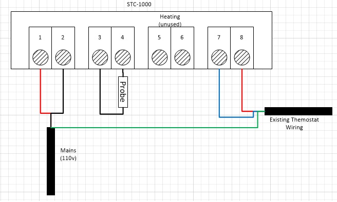
The STC 1000 seems to be the "Simple and cheap temp controller" most the home brewers are using on youtube, "many telling others how to hook it up for non-electricians". I won't go into that, if you are having trouble I would be glad to help you if I can. (If I have time)
NOTE, the STC 1000 has "relay contact" ratings of 5 amps at 120 volts. That would be fine to control a relay.. but.. a normal refrigerator used to require a 15 amp dedicated circuit (been a long time since I wired a house). Plus a "electric motor" ie: compressor draws 600% inrush of nameplate during the first milliseconds of starting. This tells you that the "contacts" are not rated to control a big motor load starting up.. the "bright flash" inside the 8 pin relay currently turning my freezer on and off confirms this. It might work for a while, but is not rated for the job.
For reliability, long service a external relay with larger contacts must be used. Like a air conditioner relay, or large relay for turning heating or motors on and off. This would have adequate contact surfaces and be made to make and break the load without burning up over a period of time, the arcing - failing contacts will also damage the compressor windings. You could use a large SSR, but then you would need a way to turn it on and off since most the ones I have seen are "low 3-28vdc" voltage on the trigger side of the relay (No SSR output on the unit), I suggest a small furnace style contactor with the 120 coil, tied with a 120 hot into one side of the contacts and the output side to the contactor. THE contacts in the external contactor relay can then turn your fridge, or heater, or?? on and off. I know, it's more money for parts, more complexity but.. rated for the job.
"Why I noticed this". (if you don't care you can skip this part)
Okay, I "stuck" my pid control off my kettle pot onto the new deep freeze for my ball lock kegs, being half blind I put the wiring that was on the type J thermocouple probe over onto it. It was working, but I had never calibrated it.
"Instrument tech" note, Thermocouples require special thermocouple wire, the only temp sensor I know of that can use "normal" copper wire is a RTD. The thermocouple works by "dissimilar metals" normally welded into a bead on the end, the two different metals "push on each other" causing a minor voltage & current to flow. If you add another metal to the circuit, say copper, you just added more dissimilar metals and are generating a unknown calibration to your PID temperature controller. It may appear to work, but as I assure you it may crash horribly wrong. Even switches or terminal strips can be incorrect, the thermocouple wire needs to go directly to the instrument. Even then the internal tuning compensates for the terminals on the back of the PID.
Even thou this was hammered into my head since the 70s, I did it anyways and near lost my beer to freezing by not paying attention. I assumed.. it was correct.
The Barber colman digital control has been around here since the 80s. Small and can do many different control schemes from following a signal to controlling, alarming. It has both SSR outputs and relay inside. I tried to program it, without a booklet on memory to use the SSR to turn on the cooling, would not do it. I had to "fix a external relay" to handle the current of the freezer compressor. That is what triggered the notice of all the Home brewers using the simpler STC 1000 (which I ordered one of off ebay)
I also ordered a backup PID off ebay to control the "kettle" and build a new control box for it. I think that barber colman unit will be on a pvc welder I am building to turn the heater on and off. ($15 conical fermenter from a HDPE blue 15 gallon barrel) And a shaper oven, and..


