STC-1000 installed into front of lid of keezer

Homebrew Talk - Beer, Wine, Mead, & Cider Brewing Discussion Forum

Help Support Homebrew Talk - Beer, Wine, Mead, & Cider Brewing Discussion Forum:

This site may earn a commission from merchant affiliate links, including eBay, Amazon, and others.

BLAKELYB

Active Member
Joined
May 27, 2013
Messages
25
Reaction score
2
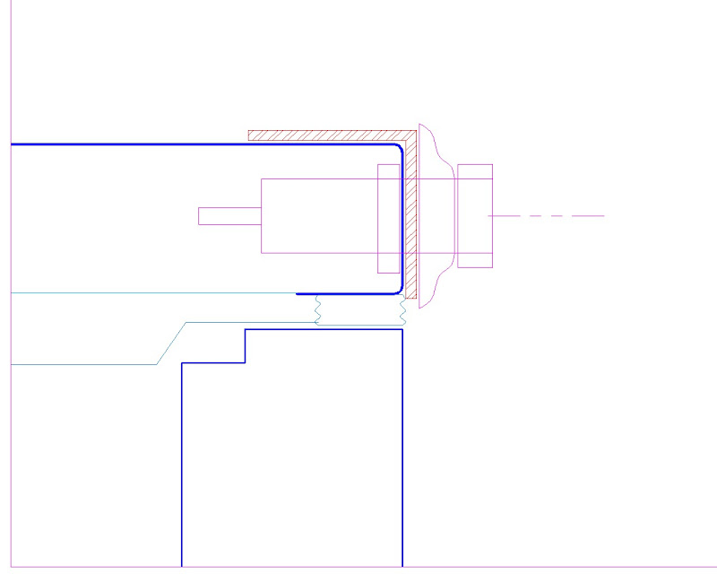
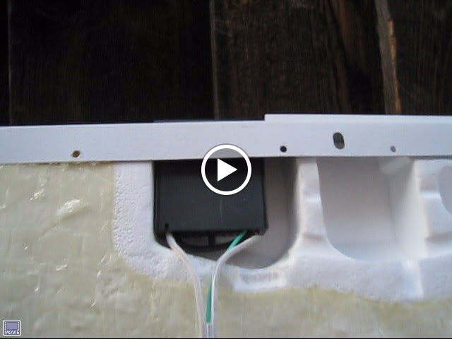
I removed the lid liner and luckily there was a space already hollowed out and it could fit the STC-1000. The hollow may have been intended for an option I did not have, like a light.

IMG_1814.JPG


IMG_1808.JPG


Below: I removed the lid and the lid liner. I had to cut off an inch of the plastic lift handle. That exposed a small sheet metal hole, which I enlarged with a sheetmetal nibbler to exactly fit the STC-1000.

IMG_1764.JPG


Below: I was able to use a 15' extension cord. The hot and neutral conductors are 16 gauge, the ground is 18 or 20 gauge. My keezer compressor only draws 150 watts (1.2 amps) so 16 gauge is plenty. I cut it into 3 pieces as shown on wiring diagram further down. 1) a short piece for the female part that the freezer plugs into, 2) a long piece for the male plug, and 3) a 5' long piece that connects to the STC-1000.

IMG_1781.JPG


STC-1000%2520wiring.jpg


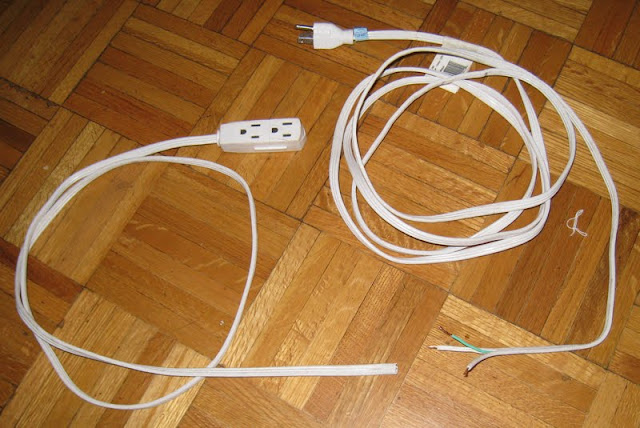
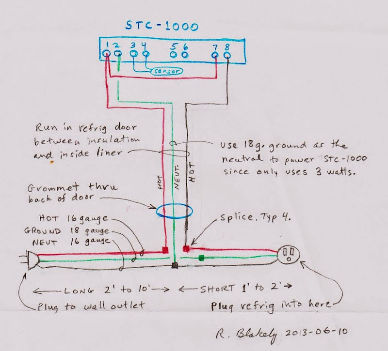
For the piece that went to the STC-1000 I changed the use of the green ground to be power for the STC-1000 which is only 3 watts, so a 20 gauge is plenty.

IMG_1794.JPG


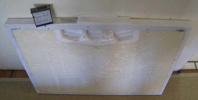
Below: The cavities were factory stuffed with fiberglass batting. I put that back in but it is not in photo. The cavities also had about 1/4" foam on the thin side. So the STC-100 is insulated all around before I clipped the liner back on the lid.

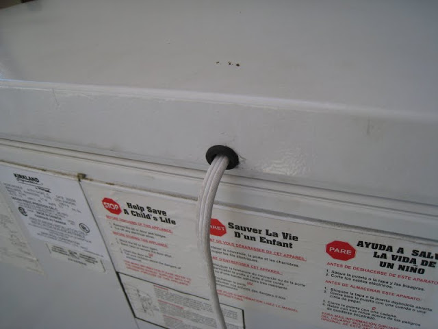
The cable did not need to be grooved or sunken into the foam. It just layed over the foam like the photo, and after I covered it with the liner, you could not tell it was there.
MVI_1795.jpg


IMG_1801.JPG


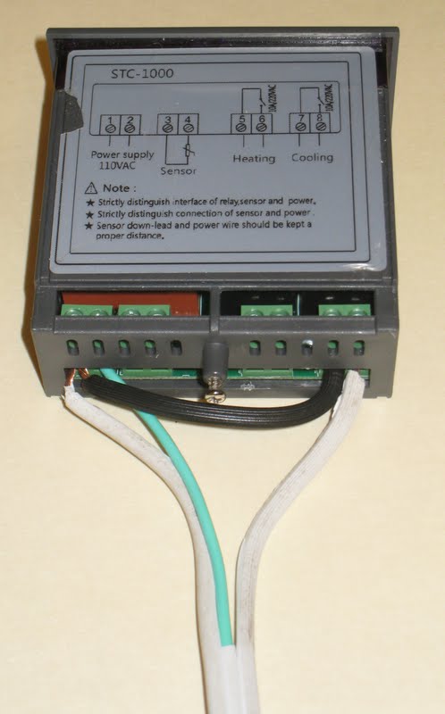
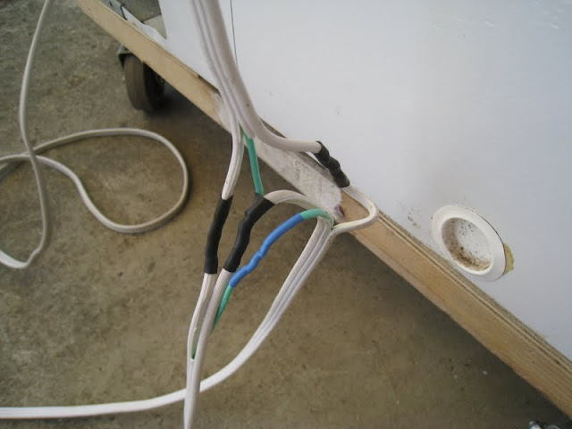
Below are the 4 splices shown on the wiring diagram. They were soldered and covered with shrink tube. No bulky boxes needed. I could have put some big shrink tube to bundle the splices.

IMG_1800.JPG


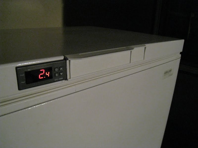
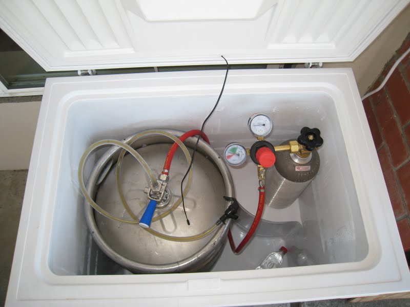
Below: The temperture sensor pokes thru the lid liner near the back (the black wire). I can put it anywhere but I like it touching the top of keg.

IMG_1816.JPG


This setup is only using about 0.4 kilowatt per day as measured by the "kill-a-watt" meter. http://www.p3international.com/products/p4400.html
I am a freak for using less energy, so I may have done things you would not do. Not having a wood collar for tap faucets, and no penetrations for a tower, keeps the heat out better. Wood conducts heat 5 times faster than polystyrene foam. The entire beer line stays cold since it is stored inside. I have been running it for about 10 days now and I am very happy with it.
 
Now I am thinking about installing a tap in the front of the keezer lid. Has anyone done that? Any links?

I measured I can easily make up to 1" hole, and have insulation around it. The 7/8" dia shank would leave enough for about 0.3" insulation at top and bottom. I would put a tiny box of insulation over the faucet when I am not using it.
 
That could work. Only thing is the base of the shank/faucet may be larger than the lid height. Having a faucet is WAY better than a picnic tap though. Highly recommend it if you can swing the $
 
I did a CAD drawing, to scale, of the faucet shank installed into my lid. The blue is the metal of the keezer. The lid is overall 1.75" thick. The red is a 2"x2" aluminum angle about 12" long, I would epoxy to the keezer metal skin to strengthen the faucet support. The purple is the shank, nut, escutcheon, and faucet collar (everything except the faucet). Looks very feasable to install it in the front, of the lid, and still leaves room for some insulation.
keezer%2520faucet-Layout1.jpg


But I just changed my 5 foot beer line to a 10 foot line and now my party faucet works much better. It works great. So I no longer have much desire to put in a real faucet. Storing my party faucet and beer line completely inside the keezer means I have no warm beer anywhere.

I read my watt meter again and lately it uses 0.3 watts per day. My previous 0.4 watts per day was during a heat wave and included the initial keg cool down. My keezer is outside. I think part of the low energy use is because i do not penetrate for a faucet. The faucet and 1" metal shank must conduct heat, so I guess the beer in the shank would get warmed up a bit. Not a deal breaker.
 
I did a CAD drawing, to scale, of the faucet shank installed into my lid. The blue is the metal of the keezer. The red is a 2"x2" aluminum angle about 12" long, I would epoxy to the keezer metal skin to strengthen the faucet support. The purple is the shank, nut, escutcheon, and faucet collar (everything except the faucet). Looks very feasable to install it in the front, of the lid, and still leaves room for some insulation.

But I just changed my 5 foot beer line to a 10 foot line and now my party faucet works much better. It works great. So I no longer have much desire to put in a real faucet. I read my watt meter and over the last 40 hours it used 0.5 watts. That equals 0.3 watts per day. My previous 0.4 watts per day was during a heat wave and included the keg cool down the day i drove it home in a hot car. My keezer is outside. I think part of the low energy use is because i do not penetrate for a faucet. The faucet and 1" metal shank must conduct heat, I wonder how much?

I have not got any taps on my kegs yet but this looks like a good idea for me, thanks!
One question is could the normal shank boss be replaced with a smaller size SS washer so that it does not protrude over the edge of the angle?
 
By shank "boss" I guess you mean the escutcheon (or flange). You are seeing the side view. From a front view only a tiny percent would be overhanging the 2" angle. If that is not good enough, I suggest measure the flange you want to use and buy the angle to suit. The drawing is to scale for all dimensions I could get, but some dimensions I could not get, like the O.D. of the flange, I just estimated. I do not own any shank or flange yet to measure off.
 
FYI you don't need the jumper between Pin 1 and Pin 7 on your STC-1000. The unit itself turns ON/OFF the outputs of Pin 7 & Pin 8 internally. Might clean up your wiring just a touch.
 
FYI you don't need the jumper between Pin 1 and Pin 7 on your STC-1000. The unit itself turns ON/OFF the outputs of Pin 7 & Pin 8 internally. Might clean up your wiring just a touch.

Pretty sure that he has it wired correctly. Power/nuetral to 1 & 2, power to 7, 8 to appliance power. If the jumper wasn't there not power would be feed to the freezer. All that is between 7 & 8 is the relay contacts
 
Matt2d is correct. Another way to say it is:
The unit includes an automatic switch between 7 and 8. Power is wired to 7, then the switch determines if the power gets thru to 8 (to the keezer). If the switch is closed the power gets thru, if the switch is opened the power does not get thru. The power must always be present at 7.
 
No you don't need the jumper. Hate to burst everyones bubbles but you're wrong about "needing" the jumper. It wont "hurt" anything, but it isn't necessary and is one more wire to come loose and short your system out. Look at the schematic on the unit. It is a switch that internally that routes power when flipped. See my wiring. It's been running perfectly for several batches.

image-1250671589.jpg
 
Mine does not work without the jumper. Looking at the schematic in the first post it does not show to be internally connected.
 
DaleHair said:
Mine does not work without the jumper. Looking at the schematic in the first post it does not show to be internally connected.

You still need power to #7. He is saying, and I agree, it is generally best practice to not jam more than one wire in the hole. Use a wire nut to split the hot wire and run it to 2, 5, and 7 separately. It will work with the jumper, but is sloppy and asking for a wire to come loose.
 
You see on the schematic picture how the switch on pins 7&8 says 10A/220VAC? Pins 5&6, 7&8 are connected internally to relays that supply power to those pins when energized. If you notice, when it changes to cool/heat mode you can hear the relays click on. Unless there are several variants of the STC-1000...mine has never used a jumper and works like a charm. Like I said, you won't hurt anything by using it, that is, unless you short the two phase wires together accidentally by jamming more than one wire into a hole made only for one. One problem you could be facing if you're saying it doesn't work without the jumper (and you have actually tried it) is a lack of sufficient current to start the compressor. They take a rather large inrush of initial current to start, so if that's the case, your unit may be faulty or damaged.

Not trying to start a pissing match, just giving my electrical engineering advice and showing you what works (flawlessly and safely) on my unit.

image-2381775203.jpg
 
No you don't need the jumper. Hate to burst everyones bubbles but you're wrong about "needing" the jumper. It wont "hurt" anything, but it isn't necessary and is one more wire to come loose and short your system out. Look at the schematic on the unit. It is a switch that internally that routes power when flipped. See my wiring. It's been running perfectly for several batches.

It is not clear in the photo but it loks like you do have something wired to contact#7?

image-1250671589.jpg
 
You see on the schematic picture how the switch on pins 7&8 says 10A/220VAC? Pins 5&6, 7&8 are connected internally to relays that supply power to those pins when energized. If you notice, when it changes to cool/heat mode you can hear the relays click on. Unless there are several variants of the STC-1000...mine has never used a jumper and works like a charm. Like I said, you won't hurt anything by using it, that is, unless you short the two phase wires together accidentally by jamming more than one wire into a hole made only for one. One problem you could be facing if you're saying it doesn't work without the jumper (and you have actually tried it) is a lack of sufficient current to start the compressor. They take a rather large inrush of initial current to start, so if that's the case, your unit may be faulty or damaged.

Not trying to start a pissing match, just giving my electrical engineering advice and showing you what works (flawlessly and safely) on my unit.

I am very surprised that they are actually internally connected, the way I read the schematic is it is a relay contact between 5&6/7&8 with no power connected internally - the 10A/220VAC is the rating of that relay.
Interested enough to check it out on mine.
 
I am very surprised that they are actually internally connected...

They are not.

Pins 5 and 7 need line voltage. There is an internal switch between 5/6 and 7/8.

You can jumper from 1/2 (sloppy and dangerous) or run a separate wire (proper).
 
Now I am thinking about installing a tap in the front of the keezer lid. Has anyone done that? Any links?

I measured I can make up to 1.5" hole, but I'd rather go smaller for more insulation around it. The 7/8" dia shank would leave enough for about 0.3" insulation at top and bottom. I would put a tiny box of insulation over the faucet when I am not using it.

I went the collar route rather than try and drill through the side of my freezer. I realize that probably doesn't help you, but I thought that would be safest as I don't have the first clue how the walls of the freezer are plumbed/wired. Tons of info on how to build a collar, just type it in the search bar.
 
I think I'm having trouble explaining myself. I need to put the pale ale down and try again tomorrow! Haha
 
GotPushrods said:
They are not.

Pins 5 and 7 need line voltage. There is an internal switch between 5/6 and 7/8.

You can jumper from 1/2 (sloppy and dangerous) or run a separate wire (proper).

Yes! This. Thank you. My "internally connected" is coming across incorrectly.
 
They are not.
Pins 5 and 7 need line voltage. There is an internal switch between 5/6 and 7/8.
You can jumper from 1/2 (sloppy and dangerous) or run a separate wire (proper).
I don't think they are either but USMCPayne seems addiment that they are internally connected to power. There is plenty of space for 2 wires in each pin, and if using a cord grip where the cable enters the box should eleminate any pull out during use.
I just want to see the confirmation of the claim :)
 
I was hoping to get more interest in people doing taps and temp controllers in the front edge of the lid. No collar. No control boxes.

I am also interested in low kilowatt hours.
 
I was hoping to get more interest in people doing taps and temp controllers in the front edge of the lid. No collar. No control boxes.

I am also interested in low kilowatt hours.

I like that you incorporated the controller into the lid, but, at least with my GE freezer, there just doesn't seem to be enough space to do a clean job of putting the faucet into the lid itself.

The lid is only 1 1/2" tall and with the need for a 7/8 hole, and space for the locking nut on the back, and the bezel on the front, I would just say make damn sure you drill your hole right the first time.

I would suspect you would see more of this done if it weren't easier to build a collar or tap through a tower setup. That said, I'd like to see how it looks if you do it.
 
The hole for the shank is supposed to be 1" dia to give some clearance. My lid is 1.75" thick over all. I suspect newer more efficient freezers have thicker insulation and maybe thicker lids. My freezer is about 10 year old.
 
Actually, you're lid is thicker than mine, providing both of us can read a tape measure correctly. At 1 3/4, I'd be more tempted to try it as there is more fudge room. I'd maybe take a really close look at the insulation and construction of the lid before I did it though. My 2 cents.
 
With my 1.75 lid I feel confident it would work. The drawing I posted gave me more confidence. With 0.25 less I would not feel confident. How old is your fridge?

Does anyone cover their taps with insulation when not used?
I was thinking a clamshell styrofoam with carved hollow.
 
I just bought my fridge a few months ago, brand new from Home Cheapot.

I do not cover my taps. If I were serving to the public and I had unused taps for an extended period of time, I would. Serving to me and my buddies out of my garage... they can drink fly guts if the beer is free.
 
This unit is consuming very little electricity. The average it uses is 14 watts, meaning it uses the same watts as something running continuously at 14 watts. I measured this with my kill-a-watt meter http://www.p3international.com/products/p4400.html
It says for the last 1900 hours (79 days) I used 26.9 kWh. That is 0.34 kWh per day, or 10.2 kWh per month. Equal to 14 watts continuously.
 
Maybe you guys can help me with a STC 1000 installation on my kegerator. My factory installed temp control does not allow me to change my desire temp down to 34°. It's stuck on like 41° to like 47° (way to warm for me). So I am going to buy a STC 1000 and replace it. My question is... if the factory temp control turns off at 41° but I have my STC set at say 34°, how does it get colder. Do I need to cut the temp control apparatus?

Also I don't want an extra outlet box it plug my kegerator into. Can't I splice into the existing power line?

Thanks

Murphy, US Army
 
I saw your thread- Danby "Kegerator won't stay cold". Try to make sure your problem is the controller before you try another controller. If it is the controller, why not get the factory replacement? If you still want a STC controller, the STC is very good and low cost. With a keezer (freezer) you do not have to be concerned about the internal controller because it will always call for cooling, which can be interrupted by the STC1000. But you have a fridge, so you will have to deal with the internal controller since it will not be calling for cooling and will keep the unit off unless you do more. Get the Danby controller wiring diagram. Maybe you can trick it into always calling for cooling, or some other trick or work around, so the internal control does not interfere. One possibility is if you can trick the internal temperature sensor to give a warm temp signal, that will keep the internal controlling calling for cooling. You need to know what type of sensor Danby uses. The STC uses a negative temperature coefficient (NTC) thermistor. Thermistors output a resistance signal, so it would be easy to trick with a cheap fixed resistor, or maybe just short it, or open it.
 
I am a freak for using less energy, so I may have done things you would not do. Not having a wood collar for tap faucets, and no penetrations for a tower, keeps the heat out better.
I agree with what you wrote but it seems that opening and closing it all the time to use the picnic taps would lose more cold air that would bleed through a well insulated collar. Did you run your meter while using the tap?

Then again things like that are not always intuitive for me.
 
Thread's a bit on the stale side, but one thing about chest freezers is they're a big box with a lid on top (as opposed to an upright freezer or fridge) and as cold air sinks, when you open the lid briefly you're not going to lose a lot of "cold" (again, as opposed to an upright cooler).

I'd say the proof of that pudding is the very low energy consumption as measured by his Kill-O-Watt over time...

Cheers!
 
Yes, the meter was running all the time, inlcuding when i tapped out beer. I only opened it for beer about 2 times per day. I think daytripper has the reason - the cold air does not fall out. But studies show (Calif. Energy Commission or U.S. Dept of Energy) that even for normal fridges with normal vertical doors,
  • opening to get things does not use much energy (this surprised me).
  • insulation has a big effect on energy
  • keeping condenser coil clean is only a moderate effect.
  • efficient fridge systems (compressor and condenser and evaporator) have big effect on energy.
Freezers are a bit better insulated than fridges.
 
Thread's a bit on the stale side...

I guess that is true if you look just at the thread age. The main points are
  1. Installing a controller readout built-in, right in the front of the keezer
  2. Avoiding the bulk and cost of a controller plug box, that most other seem to recommend.
  3. It seems very possible to put a tap in the front edge of the lid of a keezer without using a wood collar, or any collar, if the lid is 1.75" thick or more, like mine.
  4. I realized after starting the thread, the energy use on a keezer can be very low.
I don't see those 4 things getting stale as long as there are new keezer builds.
 
I don't see those 4 things getting stale as long as there are new keezer builds.

That is the catch22 of forums. Some people will get mad about 'necro posts' and the other half get mad about making new threads for thing already discussed.


Sent from my ASUS Transformer Pad TF700T using Home Brew mobile app
 
Back
Top