need to rebuild a controller

Homebrew Talk - Beer, Wine, Mead, & Cider Brewing Discussion Forum

Help Support Homebrew Talk - Beer, Wine, Mead, & Cider Brewing Discussion Forum:

This site may earn a commission from merchant affiliate links, including eBay, Amazon, and others.

BrewingCanuck

Member
Joined
Oct 22, 2018
Messages
11
Reaction score
5
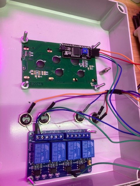
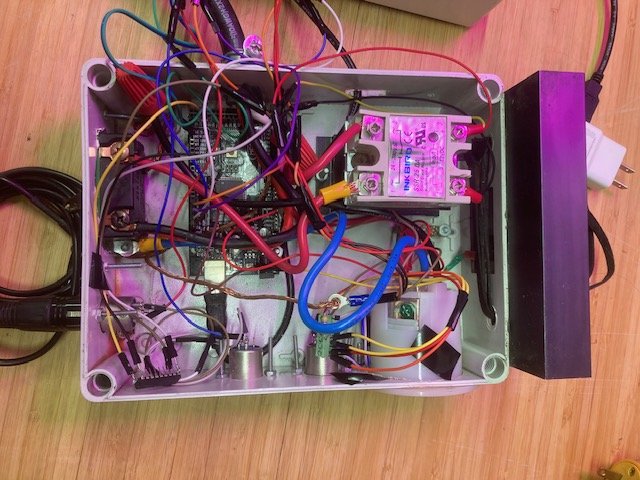
I recently bought a used brew pot and a controller was included, the PO said it was based on "https://github.com/wizbrewery/wiz-O...1Te5s2Xkt9k0o8tbUBLpOS7sshLdFIkirTj9ay2nOl1I8" what i have salvaged from this mess
1713866995406.jpeg

is
SainSmart Mega 2560 https://www.sainsmart.com/products/mega ... compatible
LCD 2004A Module https://vegaprocessors.in/blog/lcd-2004 ... hejas-soc/
4 relay module https://www.arduinolearning.com/code/5- ... e_vignette
so what can I make? Wiring diagrams would be appreciated.
System is 240v
Thank you in advance.
 
That is one of the fugliest builds I have seen around here. :eek:

Anything you build with that will be both a hardware and software project. Is that really what you want to take on? Unless you are a fairly accomplished programmer, you shouldn't try to build a brew control system based on a microcomputer controller.

Brew on :mug:
 
Who supports that software package? Is it even actively supported? Are you sure the system was actually running as designed at some point? Do you have documentation for how to operate the software on your specific configuration?

Brew on :mug:
 
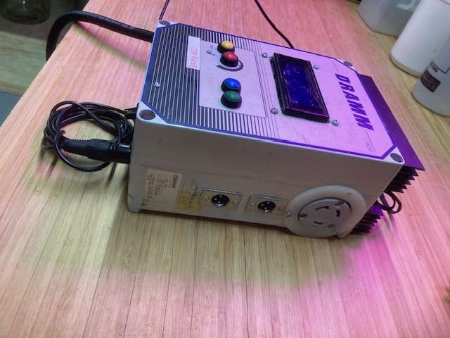
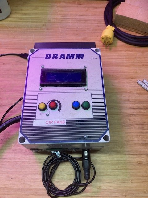
Could you show us more pictures of the box? ...side-views all around, is there a lid?
I'm wondering if it has the depth to remove the probably depricated PC board and drop in a PID such as one of the Aubers DSPR's and maybe one of the panel-mounted circuit breakers Auber carries (in lieu of contactor)... I see what looks like maybe an L6 receptacle for the element, you could hardwire your 240V input power cord, or at least a pigtail...
Just spit-ballin and wondering if that might be a route you could take.
:mug:
 
@BrewingCanuck, I agree with @doug293cz and @Broken Crow that, most likely, the digital components of this controller will probably have to go. An Auber Instruments PID could replace the existing digital control with something documented, supported, and buttoned down. Doug has posted many schematics here, one of which could serve as a guide for rebuilding your controller, possibly in the same enclosure.

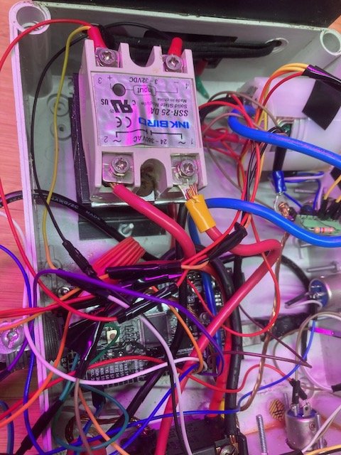
The high-voltage parts may need to be moved to a new box that can hold everything well. It looks as if, maybe, the SSR is presently mounted to a heat sink inside the fanless enclosure -- that could shorten its life because of inadequate cooling.

However, you'd need basic wiring skills to safely rebuild this thing.
Agreed! Major concern, but it can be cured by adding venting by expanding some already existing holes and expanding them, possibly with the inclusion of a small fan such as for a video card. If you want to see some confined but working fine fanless small builds, here's mine: https://www.homebrewtalk.com/threads/building-a-potentiometer-controller.731275/#post-10346359 and this one of @Agent 's that I Love! https://www.homebrewtalk.com/threads/building-a-potentiometer-controller.731275/#post-10346419
Some more pics would help.
:mug:
 
Nice heat sinks on top, but I don't see them wicking away much heat the way they are attached. That is a composite enclosure, not metal?
A good place to start on this project is to hook up the usb to a computer and have a look at the program that is on the mega board. There might be some awsome documentation (or not) in the code. Some of those pins could tell you what they control or read.
No way to trace the low voltage lines with the provided picture transitions. Can't tell if some tape is holding wires in a bundle or splicing them? Their color coding seems non standard.
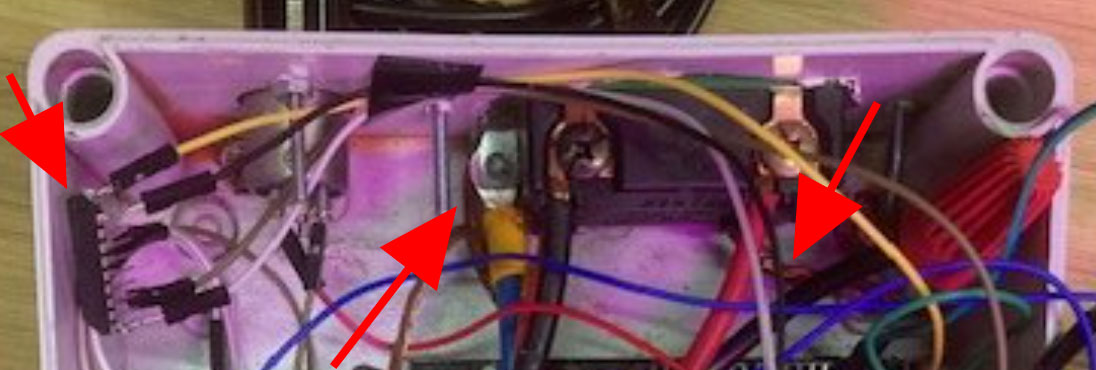
wiring-question.jpeg

That dual pole switch wire in the bottom output side (switch to wire nut) looks bare in the picture (right arrow). Tell me that is not the case!
Ground connections seem to occur at the switch screw and that contact may be concerning with all the wires.
What is the chip at the left arrow?

The AC (high voltage wiring) seems straight forward, but the close quarters and many scattered low voltage wires are concerning the way things are intermixed. If you were to revive this or use it, I would try to separate the high voltage and low voltage components more or at least bundle the low voltage wires better to protect them from inadvertent rubbing on things.
 
Re. the large heat sink, some wires exit the enclosure and appear like they probably attach to something (SSR?) externally attached to the heat sink.
 
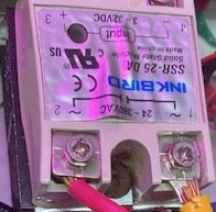
A couple things have caught my attention... The SSR is only rated for 25A which probably lead to the second thing; The wrinkling of the label and warped side suggest it pretty much overheats inside that non-ventilated space.
WarpedSSR.jpg

If you don't want to upgrade to a 40A SSR (as well as add ventilation which it clearly needs) you could probably use it for a RIMS controller or a very small batch system.
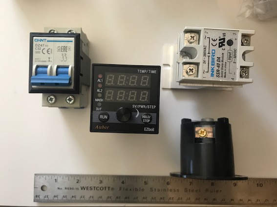
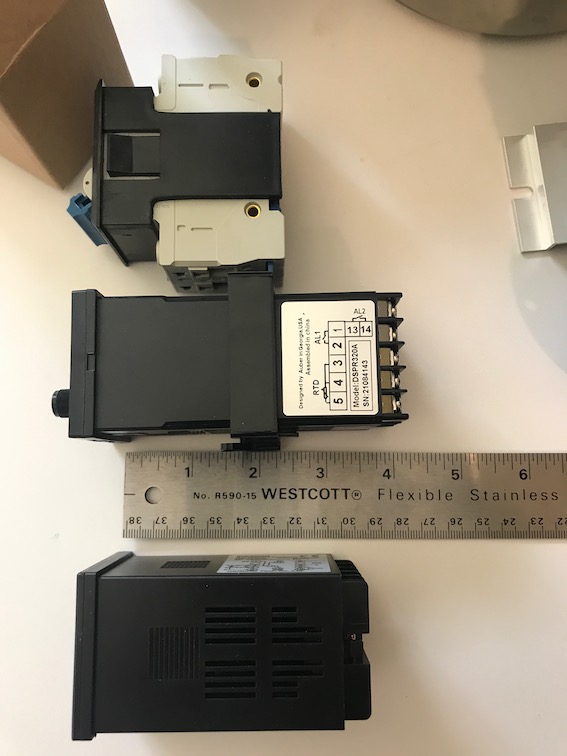
If you're not digitally-inclined and want to use some of it for the more common 'analog' systems most of build. you might have the space to do it. I was trying to get an idea of scale so I pulled out some parts and here's a vague suggestion with an Auber DSPR320 and circuit-breaker:
IMG_1608.jpeg

..of course you should also cut vent holes, maybe with a small fan.
Here's a vague idea of PID depths, the long one is the Auber DSPR320 and the shorter one is the popular Inkbird that comes in a set with the 40A SSR in the picture:
IMG_1609.jpeg

Let us know which way you're considering.
..oh, and what the heck is that big heat sink attached to? are there external components?
:mug:
 
Nice heat sinks on top, but I don't see them wicking away much heat the way they are attached. That is a composite enclosure, not metal?
A good place to start on this project is to hook up the usb to a computer and have a look at the program that is on the mega board. There might be some awsome documentation (or not) in the code. Some of those pins could tell you what they control or read.
No way to trace the low voltage lines with the provided picture transitions. Can't tell if some tape is holding wires in a bundle or splicing them? Their color coding seems non standard.
View attachment 847287
That dual pole switch wire in the bottom output side (switch to wire nut) looks bare in the picture (right arrow). Tell me that is not the case!
Ground connections seem to occur at the switch screw and that contact may be concerning with all the wires.
What is the chip at the left arrow?

The AC (high voltage wiring) seems straight forward, but the close quarters and many scattered low voltage wires are concerning the way things are intermixed. If you were to revive this or use it, I would try to separate the high voltage and low voltage components more or at least bundle the low voltage wires better to protect them from inadvertent rubbing on things.
Tried to hook up the USB to the computer some lights came on but there did not seem to be any communication between the two.
yes the wire to the switch is bare. The clip goes to the outlet yes very scary.
 
A couple things have caught my attention... The SSR is only rated for 25A which probably lead to the second thing; The wrinkling of the label and warped side suggest it pretty much overheats inside that non-ventilated space.
View attachment 847299
If you don't want to upgrade to a 40A SSR (as well as add ventilation which it clearly needs) you could probably use it for a RIMS controller or a very small batch system.
If you're not digitally-inclined and want to use some of it for the more common 'analog' systems most of build. you might have the space to do it. I was trying to get an idea of scale so I pulled out some parts and here's a vague suggestion with an Auber DSPR320 and circuit-breaker:
View attachment 847300
..of course you should also cut vent holes, maybe with a small fan.
Here's a vague idea of PID depths, the long one is the Auber DSPR320 and the shorter one is the popular Inkbird that comes in a set with the 40A SSR in the picture:
View attachment 847302
Let us know which way you're considering.
..oh, and what the heck is that big heat sink attached to? are there external components?
:mug:
I just happen to have a 40amp SSR in the box of extras that came with this (I'm still going through it) And have used Auber Pid on the controller for my 120v pot so have some experience with that.

What I would like to be able to do is set the temp and time etc.
 
Any chance the usb cable is power only? Try a usb that works with another board (data and power lines work).
 
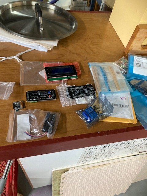
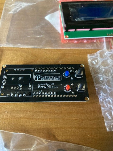
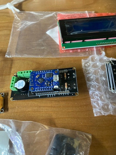
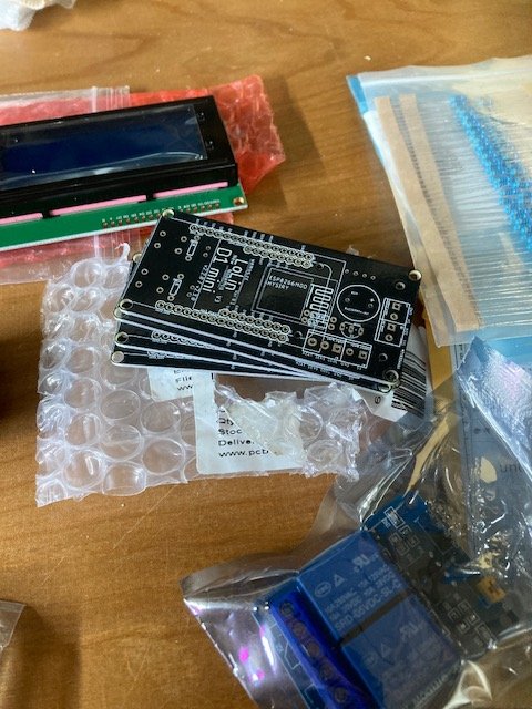
So I had a chance to go through some of the other boxes and there is a board stamped Cherryphilip compatible with BrewPiLess so far with a quick search I can find where to download code but no plans on how to build a controller with it can someone point me in the right direction? I'm just going to use the original mess as a parts donation center.
1714169391794.jpeg

1714169438905.jpeg

1714169467387.jpeg

1714169500547.jpeg

1714169523363.jpeg
 
Last edited:
Back
Top