Was gonna go propane, but...

Homebrew Talk - Beer, Wine, Mead, & Cider Brewing Discussion Forum

Help Support Homebrew Talk - Beer, Wine, Mead, & Cider Brewing Discussion Forum:

This site may earn a commission from merchant affiliate links, including eBay, Amazon, and others.
P-J,

Would you be able to update my diagram with a timer added in? I was looking at the JSL-71 from auber.

http://www.auberins.com/index.php?main_page=product_info&products_id=290

I think it'd be convenient to have it included in the CP.

Also, I've been looking at TiberBrew's build and wondering if I should be using a contactor for the elements.... Thoughts?

Thanks for your help.

Ok.. I completed the diagram for you that includes the JSL-71 timer. It is also set up using contactors. The contactors make it much easier to control the system using regular switches instead of speciality high current switches.

As always click on the image to see (and save) a full scale diagram printable on Tabloid paper (11" x 17")


I hope this help you.

P-J
 
P-J,

This looks great. I am on the run today, but when I get home later I'll sit down and study it a bit more. Thanks so much. I'm really excited about this!
 
Ok. I looked everything over and it looks perfect. I have made a parts list and now it's time to do some shopping.

I have a metal enclosure at home that measure 14"x17"x4.5". I think it would be a cool box to use for the CP, but I think 4.5 is going to be too thin. Can anyone confirm this? The face is big 14x17, so I could spread things out, but I am thinking that I would not have enough room for the heat sink and the SSR, specifically. Is there any other way to arrange the components to make this work with such a shallow box?
 
Do you plan to run the SSR's heatsink inside, or pop it out the side/top/back?

Auber doesn't list the depth on the SYL-2352, but I'm guessing you'd be tight at 4.5" - it may fit though. Your contactors are also going to be a deciding factor. Looking at a ruler and trying to remember what my panel looks like internally (I'm at work right now), I think the PID would fit, but my big contactors might not clear, especially on a back plate with DIN mounts.
 
Badnews, I was thinking about the heat sinks being inside, but i'm not opposed to them popping out the back. I'm learning as I go and wasn't sure if that was an option. They were my biggest concern, though. I didn't find a depth measurement on the PID either. I think I'll just buy my parts and see if they fit. If not, I'll just pick up a box.
 
Badnews, I was thinking about the heat sinks being inside, but i'm not opposed to them popping out the back. I'm learning as I go and wasn't sure if that was an option. They were my biggest concern, though. I didn't find a depth measurement on the PID either. I think I'll just buy my parts and see if they fit. If not, I'll just pick up a box.

Definitely mount the heatsink on the outside of the controller. I'd suggest this one External Mount Heat Sink for 40A SSR

The dimensions on the SYL-2352 PID is 1.89" x 1.89" and 3.94" deep.
The JSL-71 Timer is 1.89" x 1.89" and 3.35" deep.
I think they will fit if you have nothing behind them.

Hope this helps.

P-J
 
P-J once again comes through with the details! I second the external heat-sink. Mine is mounted externally and it definitely gets warm after a full brew session. I'd hate to have it inside and dumping all that heat into a closed space full of other electronics.
 
Those are the ones. Can you solder? Solder a wire to one end of each resistor. Solder the other end of the resistors to eachother. Slide a piece or two of shrink-wrape over everything and you're golden. Otherwise, the only other way I've seen resistors done is using a small breadboard and some jumper wires, but that's normally just for prototyping and not for long term use.
 
Yeah, I can solder. Thanks Badnews.

I was thinking it'd be that easy, but assuming has gotten me before. :)
 
Next question.

Concerning the resistors for the e-stop, are these acceptable:

http://m.radioshack.com/radioshack/...hack.com/product/index.jsp?productId=2062296"

I know what resistors do, but I'm not sure how to work with them. How does one physically wire them in? Are there resistor "holders" to keep them from moving around/touching the box itself?
Those resistors are A-Ok.
To wire them check out this post:
https://www.homebrewtalk.com/f170/brew-magic-electric-270319/index24.html#post4080976

Hope this helps you.
 
Thanks P-J.

I have a question about the RTD sensor. My intention is to monitor the wort temp leaving the herms hex coil (bad news, I know you and walker were discussing this in another thread recently). With all the probe lengths to choose from, how do I know which to choose? Could someone offer some guidance here?
 
You want 1/2" of the probe tip to be placed directly in the fluid path that you are wanting to monitor/measure. The total probe length then can be judged based on the fittings and connections that you place when you set it up.

I hope this makes sense.
 
You can use the exact same setup as Kal did for his probe in the T of his HLT and MLT - I believe it's a 1/2" T, a bushing, and a probe. It's the same setup I use, and it works great (as long as the liquid is flowing past it continuously).
 
Good call. That's what I was looking for. Thanks to both of you.

Looks like I'm going to be placing a few orders tomorrow and getting some parts sent my way! I'm excited and a little nervous. I am sure I'll have some silly questions as I go, but I'll ask anyway. The help in this thread and in all the others I've been reading has been indispensable.
 
I dropped a bunch of money today! At least, it's a bunch to me. I bought all of the components to build my control panel except for a few odds and ends.

Here's my next silly question. I've got 10 AWG wire to run from my main panel to the control panel. Once I get inside the control panel, what gauge wire do I need to use? Am I correct in assuming that everything still needs to be 10 AWG unless it's downstream of the fuses?
 
it sounds a bit lite... i would think 6 gauge off hand. how are you hooking things up?
 
I think 10 awg should be fine for a 30 amp system. I decided to install a 30 amp gfci breaker in my main panel and run 10 awg wire to an outlet and then run a plug with that same 10 awg wire to the CP. Once inside the CP, I'm thinking I should be able to run slightly higher gauge wire on the circuits protected by the fuses. I only ask because it'd be easier to work with if that's the case. I guess I just need someone to confirm that I'm right our, explain where I'm wrong.
 
I think 10 awg should be fine for a 30 amp system. I decided to install a 30 amp gfci breaker in my main panel and run 10 awg wire to an outlet and then run a plug with that same 10 awg wire to the CP. Once inside the CP, I'm thinking I should be able to run slightly higher gauge wire on the circuits protected by the fuses. I only ask because it'd be easier to work with if that's the case. I guess I just need someone to confirm that I'm right our, explain where I'm wrong.
You are absolutely right. Fuse the pump and PID circuits & you can use much smaller wiring for them. You also might want to feed the contactor pick circuit from the 10A fuse feeding the pump outlets.

With that, you only need the #10 to feed power to the contactors and then to the elements.

P-J
 
Just a heads up:

I changed the wiring diagram so that the contactor pick circuits are now wired through the pump fuse (10A). Just refresh the drawing (page 5 post #41) and save the diagram for printing.
 
Just a heads up:

I changed the wiring diagram so that the contactor pick circuits are now wired through the pump fuse (10A). Just refresh the drawing (page 5 post #41) and save the diagram for printing.

Looks good P-J. Thanks. I'll post a pic of all my new stuff in a big 'ole pile once it starts coming in. Then, I'll try to add some pictures of progress. This will be a slower build than some of the others I've seen, for 2 reasons:

1. Because I am slow by nature. LOL
2. Because I've got a little guy at home that requires my attention (and I don't mind giving it).
Now that is just plain awesome and right on the money. I applaud you in every way.

P-J
 
Thanks P-J. :)

Silly fuse question:

I'm buying glass type fuses for the fuse holder I bought at radio shack. The 10 amp fuses I see are rated at 250V. I assumed I needed them rated at 120V. Is this incorrect?

Are the 10 amp 250V fuses what I need? Does the same apply to the 1.0 amp fuses?
 
Thanks P-J. :)

Silly fuse question:

I'm buying glass type fuses for the fuse holder I bought at radio shack. The 10 amp fuses I see are rated at 250V. I assumed I needed them rated at 120V. Is this incorrect?

Are the 10 amp 250V fuses what I need? Does the same apply to the 1.0 amp fuses?
The fuse voltage rateing does not matter in this case 120V or 250V - either one will work A-Ok.
 
Ok. Next question, which is based on the last diagram P-J added to the thread.

I'm going to use 14 awg wire after the fused parts. I know that the neutral wires should also be the same gauge or bigger based on what they're hooked to.

What gauge wire do I need to use for the neutral wires between the ssr, pid, pump outlets and back to the neutral bus?

I guys I'm confused because the hot line feeding the ssr is not fused and will be 10 awg. But from the pid back is all fused.

This might be a dumb question, but remember, I'm learning here.
#14 is ok for all of the neutral circuits.
 
OK. Thanks P-J.

I'm reading that to say all, as in ALL neutrals. Even the circuits that are using 10 awg for the hot?

Just so I can understand, can you briefly tell me why.
 
OK. Thanks P-J.

I'm reading that to say all, as in ALL neutrals. Even the circuits that are using 10 awg for the hot?

Just so I can understand, can you briefly tell me why.
Auberin-wiring1-a4-4500w-30b2-pb-e-stop-3-s.jpg

Ok. No problem.

Looking at the diagram please note that the Neutral is connected to the contactor coils that draw less than one Amp total. Then it connects to power input for the JSL-71 timer > less than 1 amp. Then it provides power to the 2 pump outlets for a total draw of less than 4 amps. From there it goes on to the SYL-2352 PID input power and switch indicator lights. The total draw on the Neutral circuit will be less than 6 Amps.

Also please note that every device that uses the Neutral line has its 120V hot fused seperately. With this setup much smaller wire can be used for every device except the 240V circuits powering the elements.

That's it for the Neutral.

The 240V 10 awg circuits are the blue lines going to the contactor points and then to the elements and the red lines going to the SSR and then to the contactor points and then the elements. The only 240V powered devices are the 2 heating elements and the element indicator lights.

Hope this helps and makes sense.

P-J
 
P-J,

I noticed the HLT/BK selector switch is not on a fused circuit. Should I fuse that as well so I can step the wire size down or should I just use 10 awg wire for that piece?

Thanks (as always). :)
 
P-J,

I noticed the HLT/BK selector switch is not on a fused circuit. Should I fuse that as well so I can step the wire size down or should I just use 10 awg wire for that piece?

Thanks (as always). :)
It's fused. Follow switch #1 terminals 11 & 13. They are connected together and then go to the 10A fuse at the bottom.
 
It's fused. Follow switch #1 terminals 11 & 13. They are connected together and then go to the 10A fuse at the bottom.

Ok.... My bad. I'm was looking at the diagram before you updated it. For some reason it doesn't want to refresh.

But, I understand what needs to be done there. Thanks
 
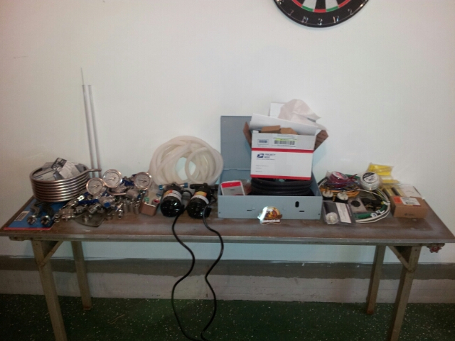
Ok. Here is a big pile of parts from all over the d*mn place. I am going to start a build thread because it'll give me a clean spot to document my progress from scratch. I'll link it once I get it set up.

P-J and others who have helped, once I get the build thread up I'd love it if you guys/gals would follow that so as I have questions you can help me there.

Pile of parts.jpg
 
Back
Top