Problem with Auber SYL-2352 PID controller.

Homebrew Talk - Beer, Wine, Mead, & Cider Brewing Discussion Forum

Help Support Homebrew Talk - Beer, Wine, Mead, & Cider Brewing Discussion Forum:

This site may earn a commission from merchant affiliate links, including eBay, Amazon, and others.

TheCarbinator

New Member
Joined
May 3, 2013
Messages
1
Reaction score
0
Location
Brisbane
So I bought the following items a couple of weeks ago to make up my HERMS temp controller.


Auber PID Model: SYL-2352P

http://www.auberins....1&products_id=4


Temp probe (PT 100)

http://www.auberins....products_id=261


Also bought the appropriate SSR and heatsink to suit.


I had them hooked up by an electrician while carefully reading the instructions.


Then when I turn it on, the temperature is showing (as far as I can work out) minus two hundred and something degrees.


That was after I changed the settings to celcius.


Then I swapped the two red wires on terminals 3 and four.


Now it is showing 636 degrees celcius (as in photo)


Has anyone come across this?


Any advice would be great!


Cheers


Andrew

2013-05-11 12.34.08.jpg
 
The programmable version (SYL-2352P) can be cryptic at first; be sure you download and read part 2 of the instructions which focuses on the programming model. I had to read through both manuals 2-3 times before I understood, and then ended up sending an email to check/clarify. Hopefully I'll be able to wire it up and try it this weekend.

To diagnose your problem, you'll have to provide more information, including key variable settings and the program you are using. The first thing I'd look at is the Sn setting; this should set to 21 for the PT100 RTD.

For example, here is what I'll be using. The Auber support person gave this a thumbs-up for my system, so hopefully it will work...

Key Variables
• Sn (input type) = 21 (Pt100 RTD)
• HY-1 (deviation high alarm) = 3F
• HY-2 (deviation low al arm) = 3F
• HY (hysteresis band) = 2F
• ALM1 (high limit absolute alarm) = 200F
• AL-P (alarm output definition) = 3 (AL1 w/process alarm; AL2 w/deviation alarm; alarm type displayed when alarm on)
• COOL = 8 (Heating, no alarm suppression, Fahrenheit)


Program
StEP1: C01 = 152, t01 = 60 (mash at 152F for 60 minutes w/Safety Start)
StEP2: C02 = 152, t02 = 1 (attempt to ramp temperature to 168F in 1 min)
StEP3: C03 = 168, t03 = 10 (mashout at 168F for 10 minutes w/Safety Start)
StEP4: C04 = 168, t04 = -95 (turn on AL1 and AL2; buzzer sounds)
StEP5: C05 = 140, t05 = 0 (hold temp at 140F until “∨” key pressed for 2 sec.)
StEP6: C06 = 140, t06 = -121 (stop)

Edit:

It looks like the SV display is showing orA6 in your photo; per section 8.1 of the SYL-2352 quick guide (last page of the first manual) this is an input error message: sensor not connected correctly; input setting wrong type; sensor defective. "For RTD sensors, check the input setting first because most controllers are shipped wit the input set for thermocouples. Then check the wiring. The two red wires should be connected to terminals 3 and 4. The clear wire should be connected to terminal 5". Hope this helps
 
For example, here is what I'll be using. The Auber support person gave this a thumbs-up for my system, so hopefully it will work...

Key Variables
• Sn (input type) = 21 (Pt100 RTD)
• HY-1 (deviation high alarm) = 3F
• HY-2 (deviation low al arm) = 3F
• HY (hysteresis band) = 2F
• ALM1 (high limit absolute alarm) = 200F
• AL-P (alarm output definition) = 3 (AL1 w/process alarm; AL2 w/deviation alarm; alarm type displayed when alarm on)
• COOL = 8 (Heating, no alarm suppression, Fahrenheit)


Program
StEP1: C01 = 152, t01 = 60 (mash at 152F for 60 minutes w/Safety Start)
StEP2: C02 = 152, t02 = 1 (attempt to ramp temperature to 168F in 1 min)
StEP3: C03 = 168, t03 = 10 (mashout at 168F for 10 minutes w/Safety Start)
StEP4: C04 = 168, t04 = -95 (turn on AL1 and AL2; buzzer sounds)
StEP5: C05 = 140, t05 = 0 (hold temp at 140F until “∨” key pressed for 2 sec.)
StEP6: C06 = 140, t06 = -121 (stop)

Borgstrom, I finally got my setup done with this PID. I was under the impression that if I set the mash temp to 152 F and the current temp was below that then once the current temp hit 152 F that the alarm would go off until I hit the alarm switch. Do I need to set one of the deviation high or low alarms? I tried switching the COOL = to 8 (from COOL = 10, default) as you have in your settings but that didn't work. Thanks for any help!
 
Sippin37: It really depends on how you have your alarm wiring set up. What problem are you having? It wasn't clear from your message what the issue is.

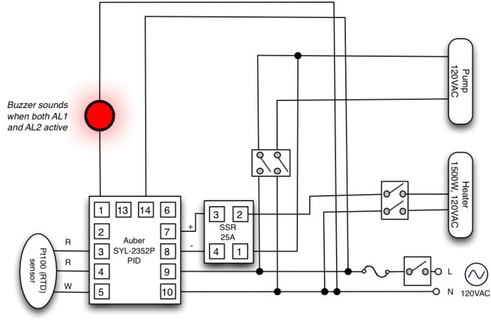
If you have the AL2 relay terminal (terminal 14) wired to activate buzzers or lights, then yes it could sound during the initial heating with COOL set to disable alarm suppression as I show above. It's important to remember that the AL1 relay simply closes the circuit between terminals 1 and 13; AL2 between 13 and 14. That's it. What happens when those relays activate depends on how you've wired your system.

For example, I have a flashing buzzer wired such that it will activate only when both AL1 and AL2 are on. I use this buzzer to signal end of mashout (step 4 above turns on both AL1 and AL2). The PID itself also has small LEDs showing the state of AL1 and AL2. I have AL-P set to 3 so that AL1 will light if I have a process (absolute limit) alarm and AL2 will light when I have a deviation alarm; this gives me some visual feedback on the state of the system. With ALM1 set sufficiently high (200F in my case) and ALM2 set sufficiently low (135F in my case) the buzzer won't sound during normal operation except at end of mashout. (FYI: I use propane to initially heat up to strike temperature in my BIAB system, and then the electric RIMS tube to maintain mash temperatures.) Here's my wiring diagram which may help you understand what I've done:

RIMS.jpg
 
Back
Top