ebay aquarium temp controller build

Homebrew Talk - Beer, Wine, Mead, & Cider Brewing Discussion Forum

Help Support Homebrew Talk - Beer, Wine, Mead, & Cider Brewing Discussion Forum:

This site may earn a commission from merchant affiliate links, including eBay, Amazon, and others.
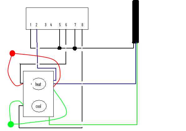
For those of you adding lamps or LEDs to signify cooling/heating, where in the circuit are you adding them? Parallel or in series? Before or after the receptacle?

In an AC circuit like this, the lamp gets wired in parallel. I expect that most people that put in an indicator wire it before the receptacle so that it shows what the control box is doing regardless to anything plugged into the receptacle.
 
For those of you adding lamps or LEDs to signify cooling/heating, where in the circuit are you adding them? Parallel or in series? Before or after the receptacle? Thanks! Almost done with my STC-1000 build. Will share pics upon completion.

You have to add them in parallel. I actually attached mine right to the receptacle screws.
 
For those of you adding lamps or LEDs to signify cooling/heating, where in the circuit are you adding them? Parallel or in series? Before or after the receptacle? Thanks! Almost done with my STC-1000 build. Will share pics upon completion.

May have been mentioned already, but there is leds built into the display.
 
You have to add them in parallel. I actually attached mine right to the receptacle screws.

So you have two wires in port 6 and two wires in port 8 (on your controller)? And then two wires on each of the receptacle screws as well?
 
Yeah they're just hard to see from across the garage. I added one red and one green so I can see easily if it is running and on what circuit.

Yeah, I put in a red and a green like other folks. Makes it very easy to see what the controller is doing. I wired mine in parallel before the outlets.
 
So you have two wires in port 6 and two wires in port 8 (on your controller)? And then two wires on each of the receptacle screws as well?

No. One switched wire from the controller (say port 6) and the black wire from the red LED go to the receptacle screw together and the switched wire from port 8 and the hot wire for the green LED go to the other screw (tab broken).

Since I didn't break the tab on the neutral side, I put the neutral in from the extension cord on one screw with the neutral from one LED and the neutral out to port 2 on the controller on the other screw with the other LED neutral. You could theoretically connect them all to the same screw, it just was easier to connect two wires to each screw.

Thank you for the feedback. I think I've illustrated what you're describing below. Care to review?

STC-1000_LED_Circuit.png
 
Yep, that's what I did. Works great for me.

Excellent! I finished building my box last night and wired the LEDs wrong, so that was the only thing holding me back from 100% completing it. I'll re-wire those lights tonight!

Thanks again for all the help, all! :ban:
 
FWIW, I thought about the indicator lights, but did not put them in my build. I do not miss them at all. I really don't need to see, minute by minute, what is going on in my fermentation chamber. I just look at the temperature display and note that it is in range, and maybe notice if it is in heat or cool mode. These things just work. I am about to build the 7th one for my homebrew club. No complaints so far, and no one has opted for lights. YMMV.
 
FWIW, I thought about the indicator lights, but did not put them in my build. I do not miss them at all. I really don't need to see, minute by minute, what is going on in my fermentation chamber. I just look at the temperature display and note that it is in range, and maybe notice if it is in heat or cool mode. These things just work. I am about to build the 7th one for my homebrew club. No complaints so far, and no one has opted for lights. YMMV.

Understandable. I just wanted a little extra bling factor to my build and felt, why not?! I'm used to a single-stage controller, so wanted to get the most out of this build and it's 100% what I want/need for my ferm chamber. Super stoked to use it this weekend.
 
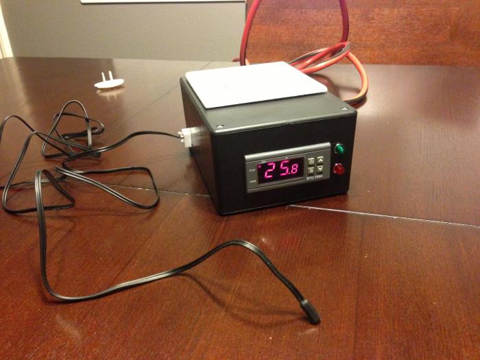
The insides aren't too pretty, but the thing works great! Basically a similar design to most people's controllers with 2x receptacles each for heating and cooling. Since the cords for my cooling devices take up space below the receptacle, I made the two bottom ones the cooling outlets and the two upper ones the heating outlets.

Also, my ferm chamber is made out of sheets of foam, and i don't want the probe's wire to go through the door, so I made a disconnect on the box out of an RJ12 voice jack. I crimped an RJ12 voice plug onto the probe as well. I've also put a short jumper through my ferm chamber's wall with jacks on either side. I can now plug my probe directly into my controller box, or plug the jumper into the box and have the probe connected to the jumper inside my ferm chamber.

I'm very happy with this build and would like to thank the OP again for making it super easy to make. I'd also like to thank pabloj13, reynolds5520, mrklueber for the help with wiring the LEDs.

TC07.jpg


TC12.jpg


TC06.jpg


TC08.jpg
 
After waiting for delivery for a month only to find I ordered the wrong part (220 vs 110) I finally have the right part and wired it all up tonight. I am excited to have temperature controll. Looking forward to my next brew to see how much it helps.
 
I built mine this AM and hooked the freezer up to it. However, it is cycling pretty often. My guess is that the keg of warm beer I just put in along with the warm 10lb co2 tank are getting it pretty warm in there. I have it set for 1 degree difference, 5min delay, 4.4 degrees C. I am considering increasing the delay and temperature difference until the keg/tank start to cool down. After that I assume it is smooth sailing.
 
I built mine this AM and hooked the freezer up to it. However, it is cycling pretty often. My guess is that the keg of warm beer I just put in along with the warm 10lb co2 tank are getting it pretty warm in there. I have it set for 1 degree difference, 5min delay, 4.4 degrees C. I am considering increasing the delay and temperature difference until the keg/tank start to cool down. After that I assume it is smooth sailing.

Where is the probe?
 
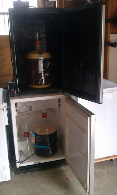
Hanging in mid air about 1/2 way between the top and bottom of the keezer. I have a cup of water in there to put the probe in that's getting to temp but it hasn't gotten there yet.
 
Hanging in mid air about 1/2 way between the top and bottom of the keezer. I have a cup of water in there to put the probe in that's getting to temp but it hasn't gotten there yet.

That's why it's cycling a lot. Put it in the water. Or put it under some bubble wrap and tape it to the keg.
 
Just picked up a controller. Couple things though. What gauge and amp wiring should I use for internal and main plug? I read that someone just cut a little more off plug wiring and used that. Also what rating outlet should I use? 15a 125 volts or 20a 125 volts. Does it matter? May be dumb questions but want to be on right track.
 
The relays on the STC1000 are rated for 10 Amps, so if you used 14 gauge wire you have head room there, and a 15A duplex outlet would be plenty...

Cheers!
 
Has anyone run the temperature probe through the blowoff tube and have it sitting in the wort while fermenting? Came up with the idea but not sure how well it'd work
 
Has anyone run the temperature probe through the blowoff tube and have it sitting in the wort while fermenting? Came up with the idea but not sure how well it'd work

That's not a horrible idea...someone try it! Probably need a long probe though.
 
Anyone see anything wrong with my wiring? The bottom end of the outlets tab is broken. Black are my main power wires, green are hot, cold, and ground, white are neutral. I plugged it in and it threw the breaker. Any help is much appreciated!

image.jpg
 
....The bottom end of the outlets tab is broken. ... I plugged it in and it threw the breaker....
Are you saying that the tab between the two Hot/Brass screws is broken off? What about the Neutral/Silver side? Does it trip the breaker immediately, or when the controller calls for cool or heat?

Make sure all your connections are tight and no shorts exist between over-stripped wires.
 
Has anyone run the temperature probe through the blowoff tube and have it sitting in the wort while fermenting? Came up with the idea but not sure how well it'd work

It used to be fairly common. Search thermowell. They come with a cork with 2 holes, one for the airlock and the other for the thermowell. You slide the temp probe into the thermowell.

They don't work as well as you would think. Temp swings WAY too big due to the time lag for the entire wort to change temp. If you control your temps manually, or just want to see the wort temp, it would be fine, but not with a controller. At least this was the responses I used to see.

images

I've heard that as well, which is why I prefer to strap the probe to the outer wall of the vessel. That will tell you that the wort is starting to reach the desired temp on the outside, and when the cooling/heating shuts-off, that bit of time where the ambient is still cooling/heating is fine because the inner-most wort hasn't reached the desired temp yet anyway.

This is also why finding the best temp differential and compressor delay is important. Otherwise you're on a roller coaster, the momentum takes you past each set-point. If you had immersed glycol, a probe directly in the wort might make sense because the temp changes are quick and efficient.
 
Anyone see anything wrong with my wiring? The bottom end of the outlets tab is broken. Black are my main power wires, green are hot, cold, and ground, white are neutral. I plugged it in and it threw the breaker. Any help is much appreciated!

If you mean that the right side of the outlet, in the picture, has the tab broken but the left doesn't, that should be working fine. You have white flowing across the tab, running the left side of the outlet and continuing to power the controller. Black is powering the controller and then is switched to the right side (both outlets) of the outlet.

Seems like it should be fine.
 
Are you saying that the tab between the two Hot/Brass screws is broken off? What about the Neutral/Silver side? Does it trip the breaker immediately, or when the controller calls for cool or heat?

Make sure all your connections are tight and no shorts exist between over-stripped wires.

The tab where my heat cool wires are connected is broken and the neutral side is not. It blows the breaker immediately. I'm most definitely not an electrician so by saying shorts by over stripped wires you mean that in the wiring nut, and in the controller itself are over stripped and should only be long enough for the controller to clamp on it? I might have over stripped and need to trim them.

Edit: I just had my wife look at it. I'm at work. I dont remember ever seeing anything about brass screws and silver screws....I broke the tab on the silver side...is my outlet toast? I mean its no big deal to buy another one at $1.50.
The side of the outlet with a silver screw should be wired as neutral and the brass screw side should be wired as hot. No. If you wired this wrong you can simply put a jumper in to replace the tab. The possibly over-stripped wires would be at the controller clamps. Copper touching between two wires would create a short and lead to a tripped breaker.

Is it a valid assumption that the other end of the power cable is pre-wired?
 
Anyone see anything wrong with my wiring? The bottom end of the outlets tab is broken. Black are my main power wires, green are hot, cold, and ground, white are neutral. I plugged it in and it threw the breaker. Any help is much appreciated!

You have the hot side and neutral sides of the outlet reversed. As mentioned, the silver screws on the same side as the ground screw are for the neutral wires, and the brass screws on the other side are for the hot wires. You'll need to break the tab between the brass screws, and make a jumper to connect the silver screws where you broke the tab off. Or just use another outlet that doesn't have the neutral tab broken.
 
You have the hot side and neutral sides of the outlet reversed. As mentioned, the silver screws on the same side as the ground screw are for the neutral wires, and the brass screws on the other side are for the hot wires. You'll need to break the tab between the brass screws, and make a jumper to connect the silver screws where you broke the tab off. Or just use another outlet that doesn't have the neutral tab broken.

I'm ignorant to this matter, but can you explain why this matters? I see 110v electric as two wires and a ground. Which of the two power wires goes where has never caused me any issues. In his illustration he has one side of the outlet powered all the time, the other is switched. Why does the hot/neutral matter?

I ask because as I said, I've never given it much mind, but I will if it's significant.
 
The side of the outlet with a silver screw should be wired as neutral and the brass screw side should be wired as hot. No. If you wired this wrong you can simply put a jumper in to replace the tab. The possibly over-stripped wires would be at the controller clamps. Copper touching between two wires would create a short and lead to a tripped breaker.

Is it a valid assumption that the other end of the power cable is pre-wired?

Do you make a jumper out of a small piece of wire? I'll trim them at the controller a bit just to be sure of it. The instructions I followed had a nut on the neutral wires, but I suppose that's not necessary as well. I bought a 10' 3 prong power cord so that was all done for me. It sounds like once I flip everything to the other side ill be in business. Thanks all! I say it a lot, but I don't know what I would do without the fine folks on HBT.
 
Back
Top