Electric Control Panel (2nd time planning)

Homebrew Talk - Beer, Wine, Mead, & Cider Brewing Discussion Forum

Help Support Homebrew Talk - Beer, Wine, Mead, & Cider Brewing Discussion Forum:

This site may earn a commission from merchant affiliate links, including eBay, Amazon, and others.

smoothlarryhughes

Well-Known Member
Joined
Nov 10, 2010
Messages
117
Reaction score
1
Location
Collegeville
I was going to build this control panel about a year ago, but I never followed through. In my original thread PJ gave me this wiring diagram, and since I haven't really been planning for awhile, I have a few questions, and I am wondering if a few things can be added to this.

First off, does anyone have a diagram to add a main power on/off switch to cut/give power to the entire panel?

2nd, should I add a second PID to monitor mash temp (once I switch to herms)? I plan on using my cooler MLT at first. I want to build the panel to use for HLT heating, use the cooler to mash, then use the panel for the BK.

From what I can tell SW7 is used to give power to the PID and timer. Is this correct?

Auberin-wiring1-a4-5500w-30a-e-stop-3a.jpg


I also came across this wiring diagram, which looks to give me info on wiring a key on/off switch.

lunchbox-a4-5500w-30a-e-stop-8a.jpg


Also, any advise on gauge wires used for these diagrams? Sorry for all the questions.

Thanks!
 
I just built a panel based on this below

I used #10 wire for the 240v components and #14 for the rest

no switch for panel power but a switch for PID power.

image-3349695382.jpg
 
First off, does anyone have a diagram to add a main power on/off switch to cut/give power to the entire panel?

There are a few on the board, but the one you posted below is almost perfect. If you want it to be a MAIN panel on/off, just move the contactor to before the terminal strips. So your power (Hot A / Hot B only) would come from the wall / spa panel, enter your control panel, and go straight to the contactor. From the load side it would then go to the terminal strips. This would allow you to turn the whole thing on or off. Wire the switch the same.

2nd, should I add a second PID to monitor mash temp (once I switch to herms)? I plan on using my cooler MLT at first. I want to build the panel to use for HLT heating, use the cooler to mash, then use the panel for the BK.

Totally up to you. I have a PID that monitors mash temp, some folks use a thermometer, some don't care.

From what I can tell SW7 is used to give power to the PID and timer. Is this correct?

False. SW7 is used to switch one of your buzzers (alarms) on or off. Power to your PID comes from push button #4. Personally, I'd get rid of it and just have your main power on / off like you mentioned further up in the thread; when are you ever going to want your panel on but your PID off?

I also came across this wiring diagram, which looks to give me info on wiring a key on/off switch.

Yup - just move the contactor to before the terminal strips and you'd have a perfect setup. The way this contactor is shown is actually fine, as the terminal strips don't actually do anything (there aren't multiple wires coming off them) but in practice, you may find yourself running wires back to the terminal strip for ease-of-install. My personal opinion is to have the contactor 'up stream' of the terminal strip, so you're killing power to the whole strip. If you only run one wire to the strip and one from it, like the drawing shows, then you could install it exactly as drawn and be fine.

Also, any advise on gauge wires used for these diagrams? Sorry for all the questions.

Wire gauge is directly related to amperage. That's why a lot of panels show a breaker (or two or three) in the panel. Whatever rating your breaker is at the wall, you have to run the associated gauge wire to your panel. Once in the panel, you can use fuses or breakers to protect the circuits and go down to smaller wiring. You don't mention what amperage any of your equipment will be pulling (are you using the 5500w elements at 240 like shown in the drawing?) but it's pretty easy to figure out what size wire you need based on the power draw of your equipment. A quick google search will pull up lists and lists of wire sizes.

Good luck!
-Kevin
 
Thanks Kevin! I plan on using a 30 amp dryer outlet (3 prong) to a 50 amp spa panel (converted to 4 wire outlet as seen here...).

power-panel-6.jpg


Does the panel need to have a 4 prong outlet? This schematic seems to use 3 prong? I was thinking of going with the package that ebrewsupply sells, but this schematic seems a little harder to follow than PJ's.

http://www.ebrewsupply.com/designs/30a-PID-2-2-2PID-Electric.pdf

Plan is to have a 5500 watt element in the HLT, and in the BK, only having 1 on at a time. I'd like to have a PID for the HLT, and a PID for the MLT, and I would just use the same PID to power the BK element. I'd like a main power switch, a selector switch to switch the element power from HLT/OFF/BK and an E-stop as well. Do you recommend having fuses or breakers inside the panel?
 
Converting 3 wire to 4 wire at the Spa panel is an oft-debated topic. I don't have enough information to really discuss it, but a search of the forums will give you plenty of opinions to either side. I can say that the picture you show, developed by P-J, has been used by numerous other e-brewers, and thus far I haven't heard of anyone burning their house down.

A PID for the HLT and MLT are good. You'll have to run your BK at manual only, unless you install a temperature probe in the BK as well and swap out the plug on your panel, as you're using the HLT PID to power the BK.

Seeing as how you're only running 1 element, I assume you'll probably have 30a to the panel. Your 5500w element will be fine - no need for an extra breaker there. Your PIDs and Pumps don't draw 30a, so unless you plan to run 10gauge wire to the pump and PID, I'd suggest using fuses to drop down. 1a fast blow fuse for the PIDs would be fine, and a 5a slow blow fuse for the pump should be fine. This would allow you to use much smaller wiring after the fuses.

If you're only running 1 element at a time, you probably don't need to worry about
 
i was just browsing around some more posts, and i think this is pretty much what I want. 2 PID's and a timer. i think the only changes i would make would be to add some lights to show when the element is kicking on and off, and and lights to show which element is selected. I was browsing your post showing your panel as well...can i ask what the total cost of the panel was for you?

mrwizard0_Brewing-SYL-2352-5500w-3.jpg
 
Thanks PJ. Are the breakers inside necessary? I know the first schematic in this post doesn't utilize them. So far I'm set on the schematic in post 6 with the 2 PID's...the only change I'd like to make is to use the second PID for the MLT, instead of the BK. I'll just use the HLT PID to control the boil in manual mode. Do you happen to have another schematic for this situation?

I appreciate everyone's help so far.

Thanks,

Jim
 
Are these e-stop buttons NO or NC? Can someone explain to me the concept?

From what I am thinking is that I would use a normally open contact, and when pressed it lets current leak out the ground, therefore tripping the GFCI in the panel. Or am I completely off base here?
 
Are these e-stop buttons NO or NC? Can someone explain to me the concept?

From what I am thinking is that I would use a normally open contact, and when pressed it lets current leak out the ground, therefore tripping the GFCI in the panel. Or am I completely off base here?
You have it exactly correct.!
 
So the implication here is that for the e-stop, "normal" means "button up" and "not-normal" means "button down," yes? That would be consistent with a push-button, but a bit counterintuitive to me, as "activated" state implies to me "not normal." Incidentally, Automation Direct sells this illuminated e-stop http://www.automationdirect.com/adc..._Illuminated_-a-_Non-Illuminated/GCX3226-120L that only includes a NC contact block, which only confuses me further.

Do I have it right in the first sentence? Am I missing something here? Thanks.
???

What?

A N/O switch has a open contact when NOT activated.!

Illuminated? What to Hell for????

Confused... You betcha...
 
So a NO pushbutton switch is open when the button is up, and closed when the button is down (activated).

A NO e-stop is open when the button is down, and closed when the button is up (activated)? So "normal" in the case of the e-stop is "button down," while "normal" in the case of the pushbutton is "button up?"

Yes, I was quite confused, but the illumination is a red herring. :)
Sorry. Your logic is twisted..

N/O = contact is open when the switch is at rest.

N/C = contact is closed when the switch is at rest (not - activated). (I just edited my error - thanks Kevin)

An illuminated switch for this application significantly complicates the application. Don't go there...
 
So a NO pushbutton switch is open when the button is up, and closed when the button is down (activated).

Correct.

A NO e-stop is open when the button is down, and closed when the button is up (activated)? So "normal" in the case of the e-stop is "button down," while "normal" in the case of the pushbutton is "button up?"

False. The NO e-stop is open when the button is up (normal condition for the switch), and closed when you mash the button down (activated). Unless you have some weird push-button switch that when you push it, it goes up. The switch you showed (the illuminated one) has a NC block, so it wouldn't work for the GFCI trip method. You could use that button for the power-flow through to the contactor method - normal condition, power flows through to the contactor coil. Mash the button, the NC block opens, power no longer flows to contactor coil, panel turns off.

Yes, I was quite confused, but the illumination is a red herring. :)

As the switch listed only have a NC block, you'd basically have the switch illuminated when normal (not activated), and turned off when activated (pushed down) - you'd have to install a NO block if you wanted to have the light turn on when activated, but if you went with the GFCI flip method, there'd be no power to illuminate the light anyways.

N/O = contact is open when the switch is at rest.

N/C = contact is closed when the switch is activated.

I think the N/C logic is backwards. N/O is open when switch is at rest (closed when switch is activated). N/C is closed when at rest (open when activated). The description above would be the same switch, which is a N/O contact block.

-Kevin
 
Thanks Kevin. So according to your definition above, "normal" position for an e-stop is button up. If I use the NC e-stop switch listed to switch a NO, DPST contactor, it would illuminate and close the contactor when the button is up, correct?
 
Thanks Kevin. So according to your definition above, "normal" position for an e-stop is button up. If I use the NC e-stop switch listed to switch a NO, DPST contactor, it would illuminate and close the contactor when the button is up, correct?

Bingo. Power would flow from your supply via any sort of keyed switch you may or may not use, through the CLOSED switch block (as Normal for an e-stop is 'up' IE not depressed) to your contactor coils. This would in-turn cause your coils to energize, causing the contactor to switch from it's normal at-rest condition of being open, to being a closed and fully functional contactor, thereby allowing the rest of your panel to be powered by your primary supply. In this condition, the e-stop button could also be illuminated.

In this configuration, the EMERGENCY STOP button is not actually being used for any sort of emergency stopping on a regular basis, but is instead simply acting as a large mushroom switch to provide power to your contactor coils. While it goes against the basic fundamentals of using a piece of emergency equipment for routine function, that's more of a SOP issue than an actual functionality issue.

As described above, your panel should function fine.
 
Thanks again Kevin. My confusion was around which state was considered "normal" for an e-stop. Once knowing that normal is up, all else logically follows.

P.S. One could also consider normal the state of lowest physical energy, i.e., the state the device would fail into, which would be down in the case of a twist-up e-stop. Hence my confusion.
 
So here is my parts list I plan on ordering in the next few weeks...anyone have any suggestions, or does this list look good for this schematic? It looks like ebrewsupply is out of the enclosure...anyone know another place i can purchase it? I am going with 1 ssr since I am controlling the bk and hlt with the same ssr (one in manual mode,one normally)http://www.ebrewsupply.com/more/enclosures/encl4x4x2.html

List:
bee9h2.jpg


Schematic:

mrwizard0_Brewing-SYL-2352-5500w-3.jpg
 
You only have some short based on the drawing, I would think these should be updated:

Ssr = 2
3 wire dryer cord = 2
 
I figured he was using them to connect the element to the panel so he would want 2 of them so each element would have its own plug
 
I am only needing one ssr, as I am using the second PID only for the MLT to show the temperature. A second 3 wire chord would help.

Thanks

Jim
 
The last schematic you attached shows 2 ssrs. You could probably use 1 if you have the output from the ssr go to both of the contactors, the selector switch would then only allow power to flow through 1 contactor
 
Order is in....

I ordered most of my parts from ebrewsupply...

Item Sku Qty Subtotal
Mushroom Button, NO Contact MUSHROOM42NO 1 $5.00
220v 40a, 110v Coil, Contactor 40a_contactor 3 $40.50
2-Way, 1 NO Contact, Switch SWITCH21NO 5 $17.50
3-Way, 2 NO Contact, Switch SWITCH33NO/NO 1 $4.50
Keyed 2-way 1 NO Contact, Switch KEYWAYNO 1 $4.50
Flashing Buzzer buzzer 1 $5.00
Blue 110v 22m LED blue-110v-22m-led 1 $3.00
Green 110v 22m LED green-110v-22m-led 2 $6.00
25a Double Pole Breaker 25ADINBREAK 1 $9.00
15a Single Pole Breaker 16ADINBREAK 1 $6.00
40a Solid State Relay SSR 40ASSR 1 $12.00
1/3m Din Rail, 1m pkg 1-3-M-DIN-RAIL 1 $6.00
DIN Rail Terminal Block TERM_BLOCK 20 $24.00
DIN Rail Terminal Seperator TERM_SEPS 3 $1.50
DIN Rail Terminal End Block TERM_END_BLOCK 2 $4.00
White 220v 22m LED white-220v-22m-led 2 $6.00
Push button, NO Contact PUSHBUTTONNO 1 $3.50
10/4 SJOOW Cable, 10 ft cut 104sjoow 1 $25.00
DIN Rail Connecting Bridge DIN_TERM_BRIDGE 2 $5.00
Element Assembly Kit Which Element 5500w Element element-package-5500 2 $170.00


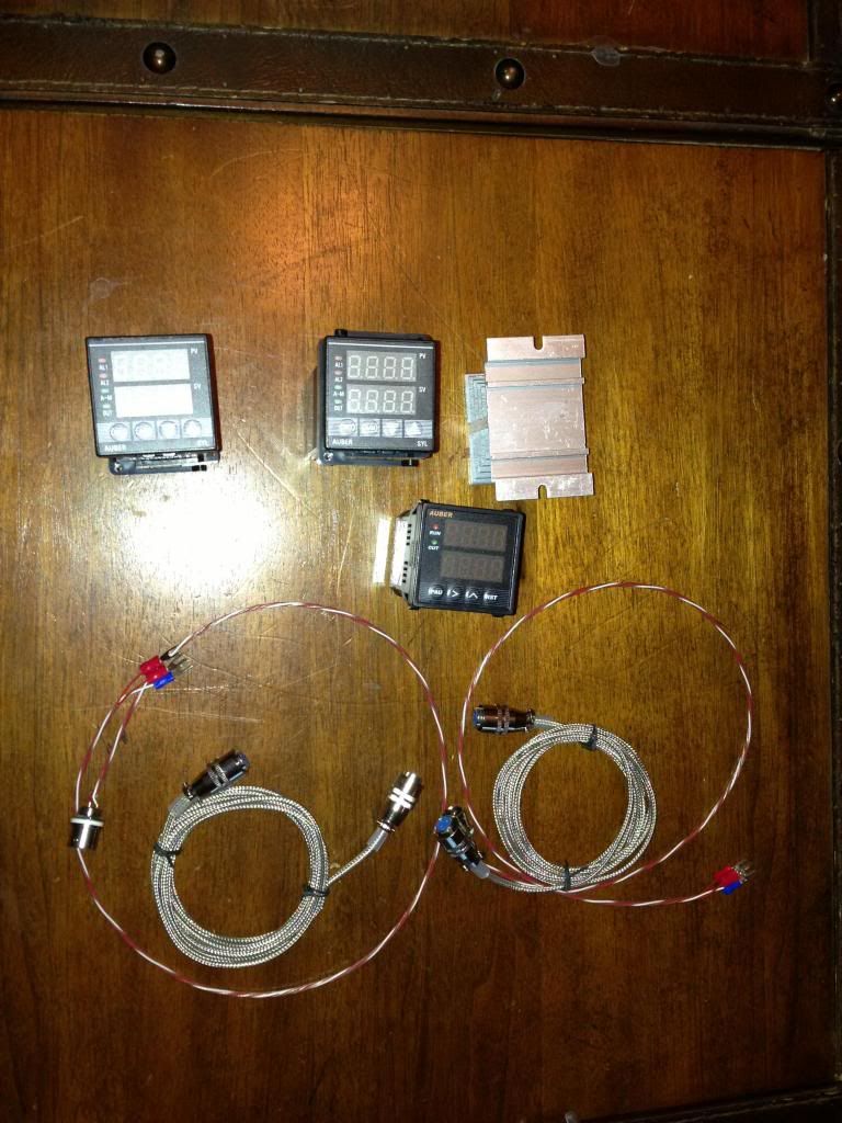
Auber:

Description Unit price Qty Amount
MULTIFUNCTION TIMER, COUNTER, TACHOMETER***
Item# ASL-51 $34.50 USD 1 $34.50 USD
1/16 DIN PID Temperature Controller (SSR control output)
Item# SYL-2352 $45.50 USD 2 $91.00 USD
120V 15A US Socket, Panel Mount, NEMA 5-15R***
Item# OUTS1 $1.95 USD 2 $3.90 USD
Liquid tight RTD sensor, 4 in, 1/4 NPT Thread Cable Option: 8 ft Deluxe Cable
Item# PT100-L100NPT $43.55 USD 2 $87.10 USD

Amazon:
2 Concord 20 Gallon Pots - 99 each with shipping - 230.94
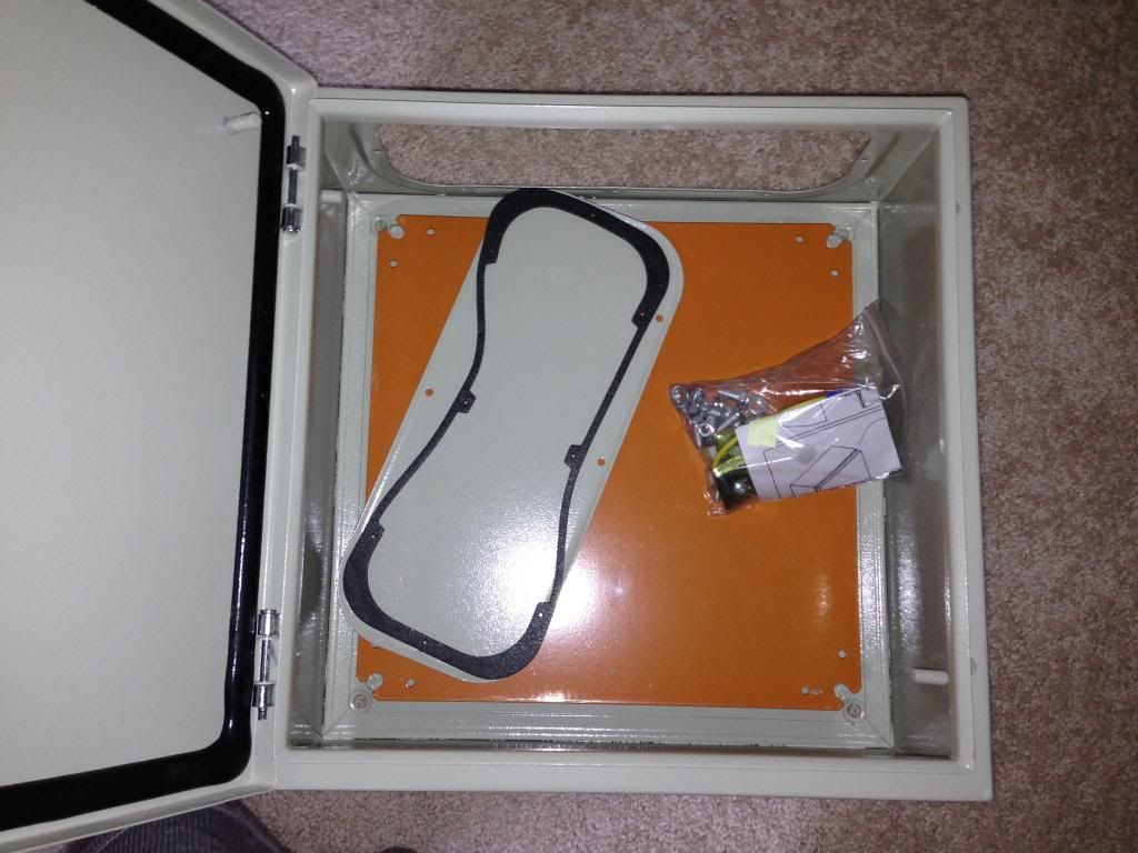
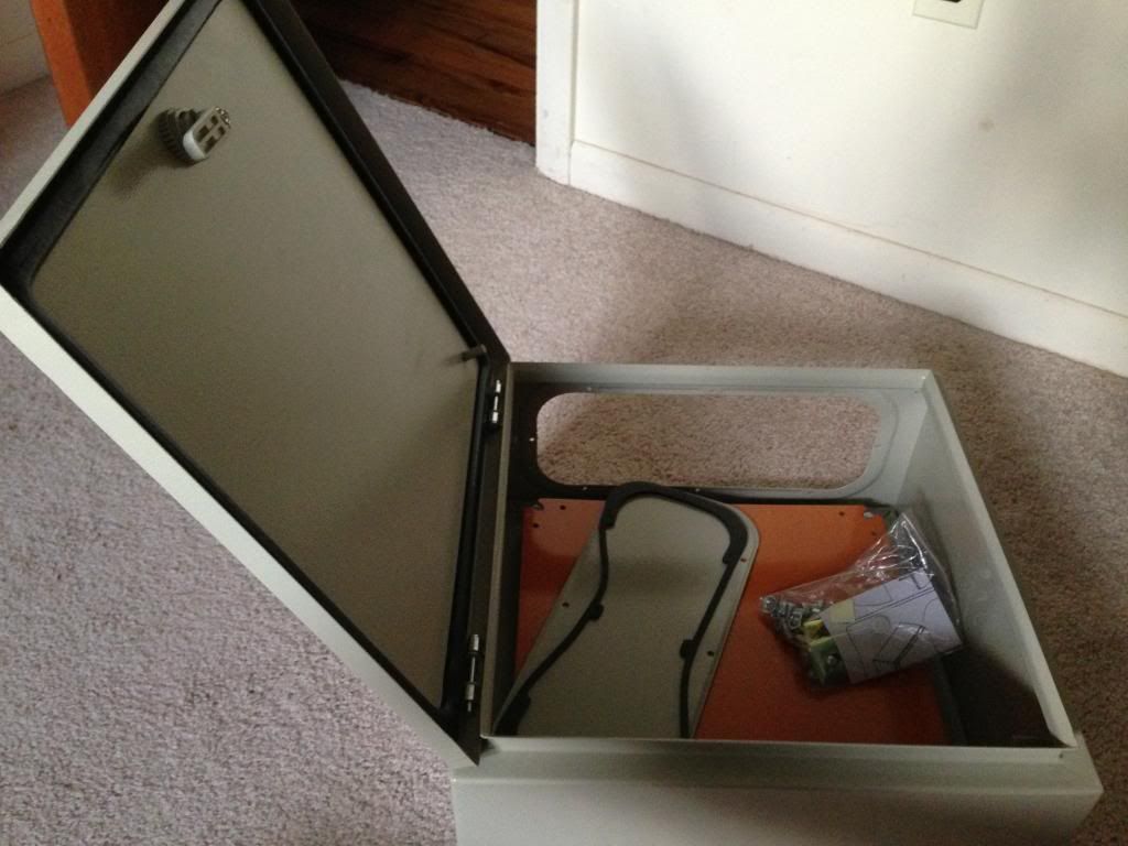
1 enclosure - 99 with shipping - 115.49
 
I had to send the probes back for the RTD's because I ordered the wrong ones...I should be getting the probes with the weldless fitting sometime next week.
 
Back
Top