Help Wiring Mini Relay

Homebrew Talk - Beer, Wine, Mead, & Cider Brewing Discussion Forum

Help Support Homebrew Talk - Beer, Wine, Mead, & Cider Brewing Discussion Forum:

This site may earn a commission from merchant affiliate links, including eBay, Amazon, and others.

SAMPLER

Well-Known Member
Joined
Apr 22, 2008
Messages
537
Reaction score
6
Location
South Portland
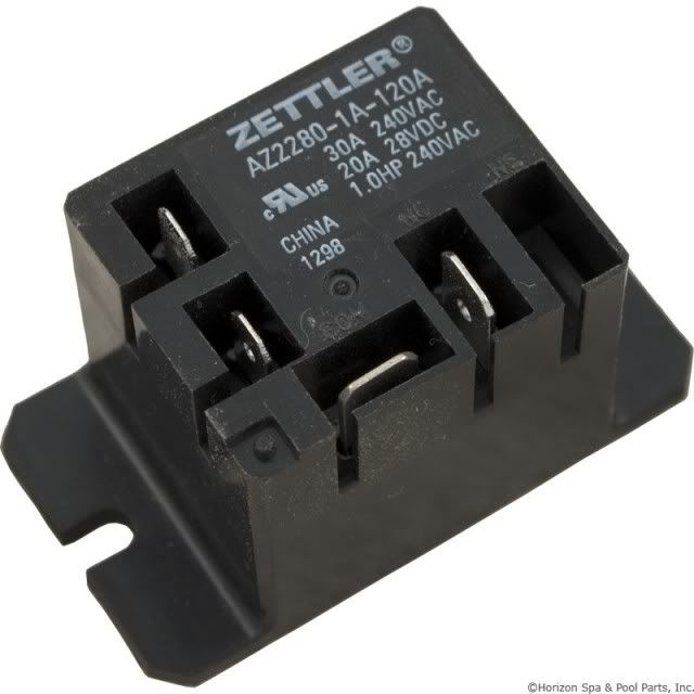
Looking to finalize my control panel build this week. Stuck in the wiring for the mini relay off the main on/off switch and after the SSR going to the element. Here is the mini relay from Auber Instruments that i am using.

60-590-1051_XL_zpse27a3a6d.jpg


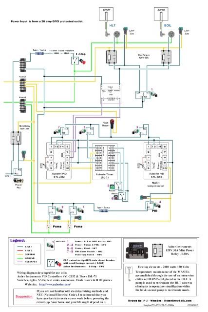
Here is a copy of my wiring plan from P-J.

Sampler-SYL-2352-JSL-71-2000w_zps0a68e9bb.jpg


Thank you for your help
 
The load would go across the COM and NO terminals; the coil is the other two.
Probably not the best way to state it since this appears to be a Single Pole Single Throw relay.

I will assume that the photo is the exact part number. Referencing your diagram, COM for both relays would connect to the SSR output HOT. NO (normally open) of each relay would individually connect to the HLT and Boil receptacles HOT.

The other two, apparently unlabeled, connections are the coil with one connected to Neutral and the other connected individually to the two HLT/Boil Select switch output HOTs.

BTW, I wasn't able to view the diagram zoomed but I don't see the required Neutrals connected to the HLT and Boil receptacles. You'll need those.
 
Thanks for the info. I was having issues figuring out which line to which connection. The coil was not clearly marked so that made this a bit more difficult.

Ps. I had added a neutral line going into each element receptacle do this should be alset.
 
Sampler,

I just waded through the diagram I made for you and realized some of the issues that you are running into. One of the things involved is that I did not show the neutral lines going to the heating elements. My bad! I've redrawn portions of the diagram and have also included the relay layout on the diagram. The relay contacts that you will be using are the common (COM) and the normally open (N/O) terminals. I hope this is more helpful.

As always - Click on the image to see and save a full-scale diagram printable on Tabloid paper (11" x 17")


I hope this helps you. Please let me know.

P-J
 
Thanks P-J! I'll play with that.

That only change i made on my end was to wire the element indicator lights from the lead going into the element not straight from the switch. This should indicate when the element is actually active from the PID and not just selected. I'm only using one element at the moment.

Thanks again.
 
Back
Top