Wiring Sanity check

Homebrew Talk - Beer, Wine, Mead, & Cider Brewing Discussion Forum

Help Support Homebrew Talk - Beer, Wine, Mead, & Cider Brewing Discussion Forum:

This site may earn a commission from merchant affiliate links, including eBay, Amazon, and others.

CoalCracker

Well-Known Member
Joined
Sep 3, 2009
Messages
1,654
Reaction score
106
Location
Macungie, Pa
Happy Friday all!

So I have been brewing with my new panel for a few months now, since the beginning my PID was not shutting off the element. Well, last night I figured it out.

Seems as though only one PID is actually controlling anything. For example. If i'm heating my strike water. I set my PID, and switch the 3 way switch to HLT. Water heats. Fast forward to the boil, I set the PID to boil and turn the switch to boil, water boils in the boil kettle. However, this is all being controlled off of the one PID. The other one just seems to be reading the temp. So the switch is working the contactors correctly to switch the elements.Is this a simple SSR snafu? Do I have my leads coming off the PIDs wrong therefore not switching control to the other PID or is there something else going on here? If I can get it so that the PIDs work with their perspective element, I'll be golden. Just not sure where I'm running into the issue. Brewing tomorrow so I'd like to try and get it resolved tonight.

Cliff Notes:

- "HLT ON"
- HLT PID is reading temp, BK PID is controlling.
- Boil PID is controlling power to the HLT element

-"BOIL ON"
- Boil PID is reading correct temp for BK
- Boil is being controlled by the BOIL PID.

So the BOIL portion is working correctly. Just not sure how it's controlling both..
 
Do you have a wiring diagram? Is it a Kal clone?

You have a PID controlling an SSR for the HLT, and a separate PID and SSR for the BK?

You have a DPST contactor with both 240v hot lines going through it between the HLT SSR and element, and another between the BK SSR and element, and control the two contactors with a 3-position switch?
 
Wiring diagram is in the link above. I got it from ebrewsupply.

You have a PID controlling an SSR for the HLT, and a separate PID and SSR for the BK?
Yup
You have a DPST contactor with both 240v hot lines going through it between the HLT SSR and element, and another between the BK SSR and element, and control the two contactors with a 3-position switch?
Yup
 
Happy Friday all!
Cliff Notes:

- "HLT ON"
- HLT PID is reading temp, BK PID is controlling.
- Boil PID is controlling power to the HLT element

-"BOIL ON"
- Boil PID is reading correct temp for BK
- Boil is being controlled by the BOIL PID.

So the BOIL portion is working correctly. Just not sure how it's controlling both..

If the HLT PID is correctly reading the HLT temp then what SSR is it controlling? None?
If the Boil PID is controlling power to the HLT element then one of two things is incorrectly wired. Either the PID to SSR circuit is wired incorrectly (Boil PID to HLT SSR) or the SSR to Boil Element is wired incorrectly (Boil SSR to HLT element).

Good luck. Pictures might help.
 
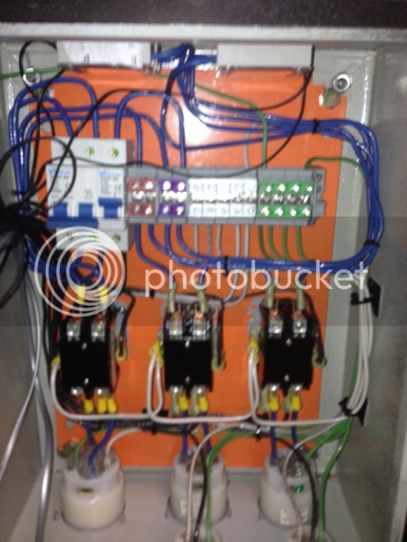
Nice wiring job! The picture is blurry, but usable.

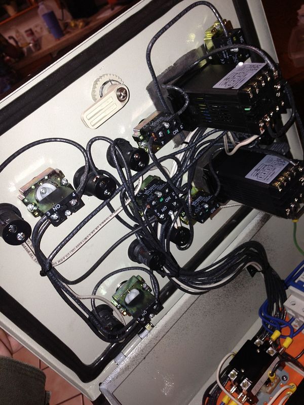
Can you get one of the back of the door where the controls are?
 
I think you are going to need a little more detailed pics of where the wires start and end (especially the black wires) . It's hard to tell in the big bundles exactly what wire goes where.
 
The diagram looks correct.
each PID connected to each SSR.
3-way switch controls whether the BK OR the HLT contactor is enabled.

Check the wiring from each PID SSR output to each SSR input.

It should be easy to test/check the operation using the PIDs.
Set one PID to OFF (using PV or manual mode 0%).
Turn the other PID ON using PV or manual mode and verify that the appropriate element is ON when enabled by the contactor and the other element is OFF even when it is enabled by the contactor (and vise versa with the other PID)
 
I agree that the wiring diagram looks good. Pictures of the back of each PID and the SSRs / contactors would be helpful. Unfortunately it looks like you ran everything with the same black wire, so it's going to be a bit difficult to trace all the lines.

I'm guessing that your switch was not wired correctly, or you somehow have the lines between your SSR and PID piggy backed / shorted so that one PID is powering both SSRs.
 
I would agree With BadNews double check your wiring. If it is wired as the diagram shows it should work properly. There must be a wire crossed somewhere. Make sure that your wires on the switch are on the correct NO terminal.
 
Well, let's think about this...

-"BOIL ON"
- Boil PID is reading correct temp for BK
- Boil is being controlled by the BOIL PID.


Okay, so the Boil PID is correctly connected to the Boil thermo probe and the PID is correctly connected to the Boil SSR, which is connected to the Boil element.

First, you need to verify that the HLT SSR is not doing anything at this time, nor is the HLT element heating up.

- "HLT ON"
- HLT PID is reading temp, BK PID is controlling.
- Boil PID is controlling power to the HLT element


The Boil PID is somehow sending signals to the HLT SSR, which is activating the HLT element.

Or the Boil SSR is somehow sending electricity to the HLT element.

Now, if the HLT SSR and the HLT element were NOT firing when in BOIL mode, then that must mean that when you switch from BOIL mode to HLT mode, that switch is also moving the Boil PID SSR signal from the Boil SSR over to the HLT SSR.
 
The light on both SSRs are always on. If i'm running the HLT, the BK ssr light will be on and vice versa. However, only one element is running at a time. So, sounds like a switch. Or, the leads coming off the side of the contactors are mixed up. Could that be an issue? Pretty sure that's where that switch leads.
 
The light on both SSRs are always on. If i'm running the HLT, the BK ssr light will be on and vice versa. However, only one element is running at a time. So, sounds like a switch. Or, the leads coming off the side of the contactors are mixed up. Could that be an issue? Pretty sure that's where that switch leads.

Hmm. So the Boil PID is sending signals to both SSRs, but since you have a switch that energizes either the coil on the Boil contactor OR the coil on the HLT contactor, that's why both elements aren't also firing at the same time.

And it sounds like the HLT PID is sending signals to both SSRs as well?

Well, that's a problem allrighty.

Sounds like the wires going from connector 6 from both PIDs are going to the positive side of both SSRs. Those wires need to be separate circuits from each other.
 
CoalCracker said:
- "HLT ON"
- HLT PID is reading temp, BK PID is controlling.
- Boil PID is controlling power to the HLT element

-"BOIL ON"
- Boil PID is reading correct temp for BK
- Boil is being controlled by the BOIL PID.

The only option I can see is that your ssr output from you pid wires are shorted together otherwise each pid would only change its specific ssr. Are you sure that this is the correct diagnosis? What did you do to test that the boil pid is controlling the hlt element?
 
SO... I way overthought this. I swapped the SSR wires from the PID and everything is working correctly now. I had the HLT SSR working on the Boil PID. Did a brew this weekend and everything went as planned. Minus some of my own boneheaded mistakes.
 

Latest posts

Back
Top