g-love's e-herms brew rig build

Homebrew Talk - Beer, Wine, Mead, & Cider Brewing Discussion Forum

Help Support Homebrew Talk - Beer, Wine, Mead, & Cider Brewing Discussion Forum:

This site may earn a commission from merchant affiliate links, including eBay, Amazon, and others.

g-love

Well-Known Member
Joined
Jul 2, 2010
Messages
658
Reaction score
113
Location
Warfordsburg
I started this with a bunch of questions in another thread because I was originally going to build a propane rig, but decided it'd be nice to use electric. I decided this for two main reasons: 1. I wasn't comfortable using propane inside (personal choice) and 2. I really like the idea of how quiet electric brewing is.

I have only done extract to this point, I tried an all grain BIAB one time that did not end well (my fault). I tend to jump into hobbies and go a little crazy with "stuff," and this has been no different. I have to say I've enjoyed the planning and building that I've done so far as much if not more than brewing in general.

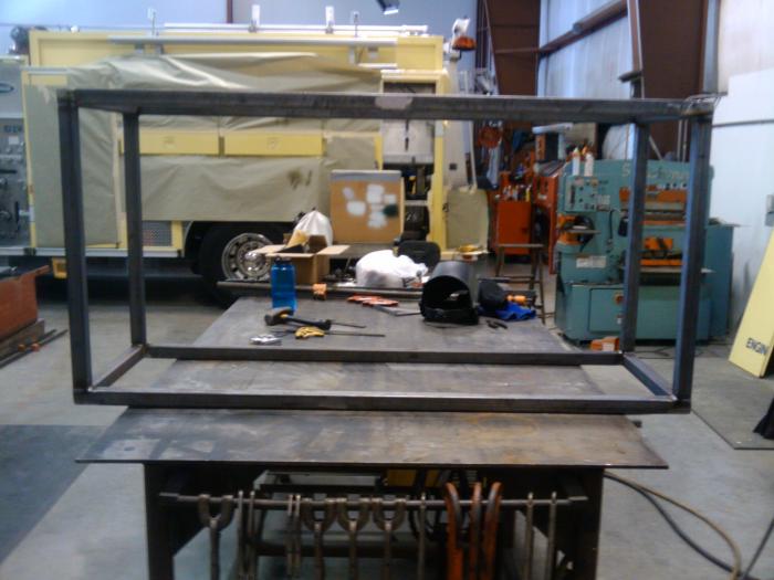
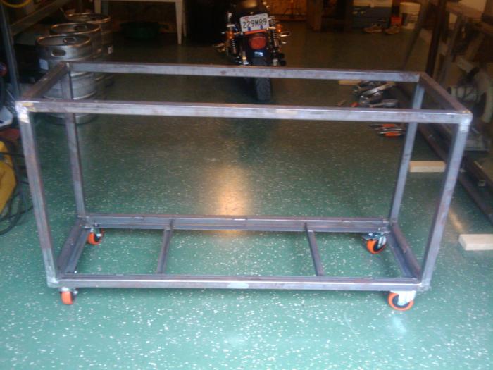
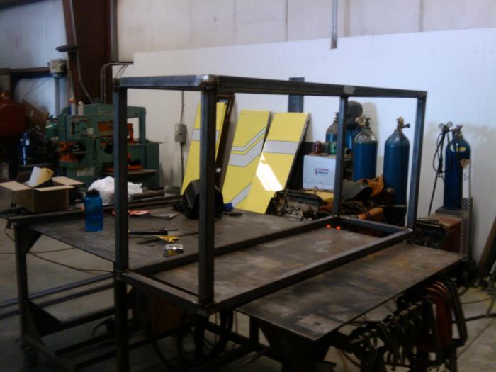
My build here is a 3 vessel e-herms build with (2) 4500 watt elements. I already had a basic stand built to accomodate the propane set up I was going with, so I am using that. It's overbuilt, but whatever. I took the measurements from jlandin's propane build and I really liked his idea of wanting to keep everything within the plane of the stand itself for storage. I build a brew closet in my garage that this slides into perfectly when I am not using it.

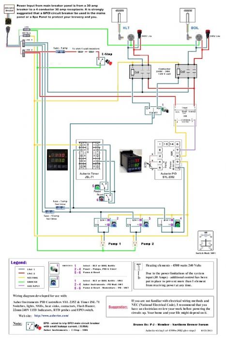
The following pics show the final wiring diagram (THANKS P-J!) that I went with and the build of the stand itself. That's where I am at this point. I've collected all of my parts, with the exception of a few odds and ends. This will be a slow one, but I'll keep this updated as I go.
Auberin-wiring1-a4-4500w-30b2-pb-e-stop-3-s.jpg


Stand wo wheels.jpg


stand wo wheels 2.jpg


Stand w wheels.jpg


Wilson on stand.jpg
 
Here is the stand with pumps and chiller mounted and the control panel mount that I went with. I wanted to keep the pumps "inside" the stand and covered by the diamond plate for splash protection.

Stand top w pumps.jpg


Stand front w pumps.jpg


CP mount.jpg
 
I chose to use a plasma cutter for my kegs and I'm really happy with the job that it did (there is an unpictured 3rd). I also inlcuded a pic of the grain mill that I motorized. I stole this design from jpalarchio. I like the fact that I can hang it on the wall in my brew closet when I'm not using it and it doesn't take up floor space.

Kegs cut w plasma.jpg


Malt mill 2.jpg
 
Looking great so far. The diagram is a little hard to read as it's the small image version - So...

As always - click on the image to see (and save) a full scale diagram printable on Tabloid paper (11" x 17"):


Hope this helps.

P-J
 
P-J, you have been helpful to the point that I feel like I owe you money! :)

I can't thank you enough.
 
Looks great. I'm wondering whether you will have any trouble with the pumps, given that you will not be getting much help from gravity with such a short drop. Only one way to find out. :)
 
Any chance you have a part number on that coupling on the grain mill?

These are the parts I used with my JSP mill:

1 6408K113 Flexible Spider Shaft Coupling Hub, 3/8" Bore, 1-5/64" Od, Without Keyway
2 6408K711 Flexible Spider Shaft Coupling Hub, 1/2" Bore, 1-5/64" Od, With Keyway
3 6408K84 Buna-n Spider For 1-5/64" Outside Diameter, Flexible Spider Shaft Coupling Hub

McMaster-Carr part numbers
 
Any chance you have a part number on that coupling on the grain mill?

Unfortunately, I don't. I've had them laying around forever and just recently took the time to motorize the mill. The ones Spartan put up look good though.
 
Looks great. I'm wondering whether you will have any trouble with the pumps, given that you will not be getting much help from gravity with such a short drop. Only one way to find out. :)

Thanks man. To be honest, I'm also wondering that. :drunk:

I really like how they are tucked in there, so I figured I'd give that placement a shot and if they don't work well, I'll relocate them.
 
I'm working on locating all the holes for my kegs and I should have those drilled and punched this weekend. Then, they'll be headed to my buddy. He's a welder and will do it for free, but it'll be on his time frame. However, I figure I can start on my control panel while he's working on the kegs.

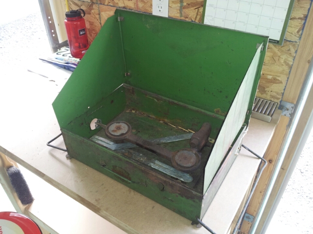
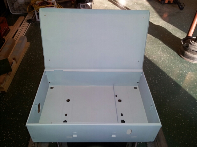
Speaking of control panel, you guys will probably think I'm a little off, but I'm using the metal box from an old propane camp stove for the panel itself. It's shallow, but my measurements say that everything I have planned will fit inside just fine. The PID will be close, but it'll fit.

Here is what it started as vs. what it looked like after I cut all the junk out, sand blasted it, and primed it. I'm not sure what I want for the finish. I will paint it of course, but I was thinking about 1/16 diamond plate on the face. Not sure yet.

CP originally.jpg


CP after primer.jpg
 
ForumRunner_20130704_120402.jpg

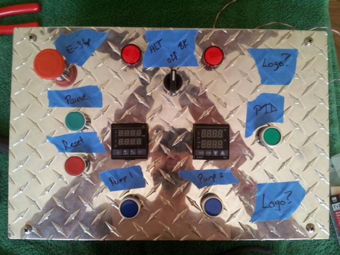
Slowly but surely. The front of my panel is now assembled. Going to paint the panel box today and mount all the other internals this weekend.
 
I believe your mount for your control panel is upside down... and I wouldnt suggest it... I purchased that model off of Amazon too, and I know the speicific model because it is the only one with that unique V shape to slide the 'tv' onto and off of the device. (hence how I know it is upside down) The arm is rated for 33 LBs and when I put my control box on it it started to bounce like pamela anderson...well... you get the point. I now have to un attach the stupid thing which is behind my mounting plate behind all my finished wiring... needless to say, I am not happy with it...

I purchased a similar unit that can hold 50 LBS and hope to install it this week, I will let you know if it is any better, it still has the single beam mounting arm which I was looking for.
 
So looking at the wiring diagram, you are using one PID to control two heater elements. Does this mean that you have to physically move the temperature probe from one kettle to another, or do you have two that you just plug into the control box? Would there be any way to have both plugged into the control box and use a switch, similarly to the way that you switch between elements? Nice looking build. Just starting to plan mine.
 
So looking at the wiring diagram, you are using one PID to control two heater elements. Does this mean that you have to physically move the temperature probe from one kettle to another, or do you have two that you just plug into the control box? Would there be any way to have both plugged into the control box and use a switch, similarly to the way that you switch between elements? Nice looking build. Just starting to plan mine.
The wiring plan is set up to require only a single temperature probe that is placed in the HLT. The PID is a SYL-2352 unit that has a manual mode. Control of the BOIL is accomplished by regulating the percent of power delivered through the use of manual mode.

Hope this makes sense.

P-J
 
OH! That makes sense. Very nice design without redundant equipment. Seems pretty streamlined and cost effective that way.

Is there a way to link the timer to the PID so that when the time goes of (i.e. after 1 hour of recirculating mash, or 1 hour of boil) that the timer would trigger the PID to shut off the element?

**EDIT**
Nevermind, I think? Looks like the 2352P has a ramp/soak feature? Can this be used for that purpose?

**EDIT EDIT**
HAHA, sorry, just checked out Auberins.com. The 2451 seems to do this (on/off with timer). Is the main difference between the two the programmable steps function? Seems like the 2352P would be great for step mashing (or mash out) on a eHERMS where you didn't have to monitor at all really, pretty much automated while the 2451 you would need to continually program the temperatures and times. Am I understanding this correctly. Sorry if I'm off topic!
 
Hi there I dont want to hi jack this thred but was wondering if P-J could help me with a wiring diagram .placed my order with Aubor today im buildig to control BIAB with steo mash . Im also running pump continously through mash with RTD in a Tee junction in lid before the sparge sprinkler head. I will also be running 4400w element . Your help would be much apprichated. I wouod be willing to pay for a full digram

Heres what I ordered
------------------------------------------------------
1 x 25A SSR (MGR-1D4825) *
2 x External Mount Heat Sink for 25A SSR (HS25ET)
1 x LED Indicator, 22 mm, 120/240V (IND-1) thats
* * * * Power Voltage Option 240V AC/DC
* * * * LED Color Option Green
1 x Selector Switch, 2-Position Maintained 1NO 1NC, 22mm (SW2)
1 x Flashing Buzzer, 110 or 240V AC. 22 mm (FLBuz) *
* * * * Power Voltage Option 240V AC/DC
1 x 25A Solid State Voltage Regulator, High power SCR, *SSVR (SSVR25A)
* * * * Rheostat Option For 240V AC, 50Hz
1 x Liquid tight RTD sensor, 1.5 inch, 1/2 NPT Thread (PT100-L401/2NPT)
* * * * Cable Option 8 ft Deluxe Cable
1 x LED Indicator, 22 mm, 120/240V (IND-1) *
* * * * LED Color Option Red
* * * * Power Voltage Option 240V AC/DC
1 x 1/4 DIN PID Temperature Controller (SYL-43X2) *
* * * * Output Configuration Option SYL-4352P SSR Control, Ramp/Soak
1 x Selector Switch, 3-Position Maintained 2 NO, 22mm (SW3)
1 x Emergency Stop (E-Stop) Switch, 22mm (SW6) *
 
I believe your mount for your control panel is upside down...

Good catch. You are right, it was upside down. I had mounted it on the stand, but not on the panel yet and I wasn't paying attention. I have flipped it since then. Since I already bought it, I'm going to see how it works before I look into an alternative.

However, if you have any input on the new one you bought, I'd be interested just in case this one doesn't work out.

Thanks man!
 
The 2451 seems to do this (on/off with timer). Is the main difference between the two the programmable steps function? Seems like the 2352P would be great for step mashing (or mash out) on a eHERMS where you didn't have to monitor at all really, pretty much automated while the 2451 you would need to continually program the temperatures and times. Am I understanding this correctly. Sorry if I'm off topic!

I can't answer this because I haven't researched it. I went with the 2352 because it's what many people use and what P-J suggested for use with his diagram. No worries on the off topic. I'd be happy to hear the answer if anyone else knows for sure. :mug:
 
ForumRunner_20130801_121051.jpg

hlt - don't know how to rotate pics from my phone. I'll try to "right" that later.
 

Attachments

  • ForumRunner_20130801_121118.png
    ForumRunner_20130801_121118.png
    390.3 KB · Views: 421
I have a very basic question about the wiring of the e-stop that I feel a little silly asking, but here goes. I am assuming I'm using the N.O. set of contacts, hot in one side and ground out the other (like the diagram shows)? My thinking is that there is no current flow until the kill switch is depressed and then it's thrown to ground, kicking the breaker...?

Am I right on this? If not, please explain.

Thanks!
 
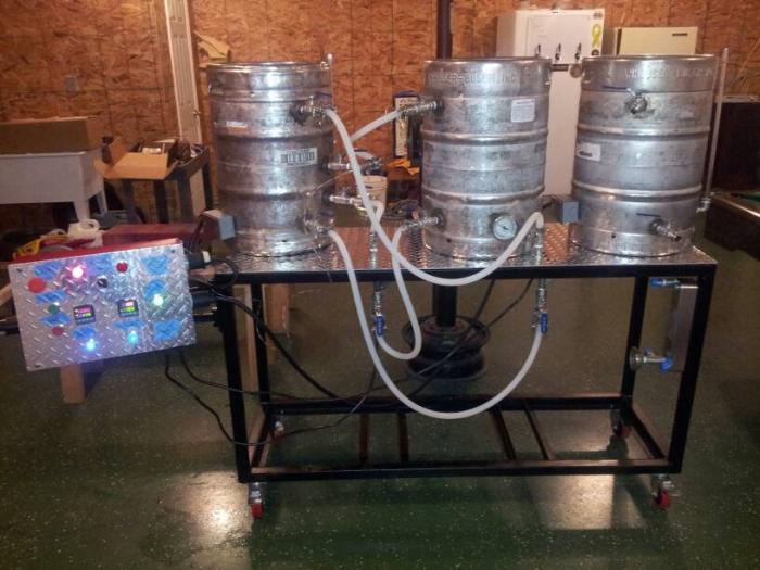
Oh, and here is an updated pic with plumbing/houses. I'm really not sure the current pump set up is going to work, but I'm going to try it like that first. If it doesn't, I'll just relocate them lower.

ForumRunner_20131129_132433.jpg
 
I have a very basic question about the wiring of the e-stop that I feel a little silly asking, but here goes. I am assuming I'm using the N.O. set of contacts, hot in one side and ground out the other (like the diagram shows)? My thinking is that there is no current flow until the kill switch is depressed and then it's thrown to ground, kicking the breaker...?

Am I right on this? If not, please explain.

Thanks!
Absloutely - Right on the money.
 
Fast response P-J. I thought I was correct, but once that self doubt creeps in, it's a killer. haha

Thank you!
 
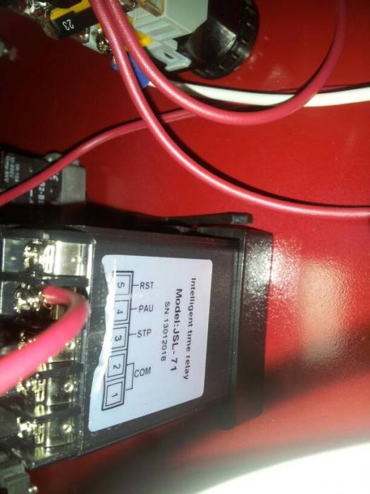
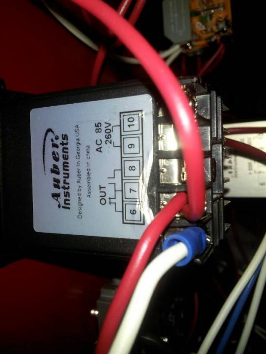
P-J, if you have a chance, could you double check the diagram wiring for the timer against the pictures of the timer shown here? I feel like there is a mistake (maybe in how Auber says to wire it on their site). I'm thinking some of the connections are off based on the terminal labels on the timer itself. I'm not challenging you, just asking if something got mixed up.

Any help is much appreciated, as always. I'm aiming to finish the wiring today if possible.

1388251870832.jpg


1388251885373.jpg
 
168555d1388251887-g-loves-e-herms-brew-rig-build-1388251885373.jpg


The wiring layout printed on the controller in this image is correct.
Termial #7 is the output common, #6 is the N/C & #8 is the N/O.

Hope this helps.

P-J

Edit: BTW - Some of the diagrams from Auberins are not quite right. Your layout seems A-Ok.
 
Ok. The control panel wiring is done and it works like a charm! I ran a system test with water and I have some small leaks to fix, but overall it went really well.

The pumps work well right where they are. I was a little worried that the placement would cause an issue, but they didn't even blink as I was using them.

This rig is damn near functional. It's taken forever, but this has been such a fun and rewarding project.

Thanks again to P-J and the others who have answered questions along the way.

1388507436736.jpg


1388507449870.jpg


1388507480129.jpg
 
Back
Top