Hybrid Kal + automated water valves

Homebrew Talk - Beer, Wine, Mead, & Cider Brewing Discussion Forum

Help Support Homebrew Talk - Beer, Wine, Mead, & Cider Brewing Discussion Forum:

This site may earn a commission from merchant affiliate links, including eBay, Amazon, and others.

Stephonovich

Well-Known Member
Joined
Jun 11, 2011
Messages
237
Reaction score
8
Location
Austin
So, I'm not hugely interested in building a full on automated build; plus Kal's system is pretty solid looking.

What I would like, however, is to do a small automated water measuring system for the HLT, and possibly to flow balance for fly sparging.

I found these flow meters, which while perhaps not the fanciest things (water makes turbine go roundy-roundy, causes pulses via Hall Effect), look like they'd work for pre-BK stuff. 80C is 176F, which is more than I can foresee putting into the MT. 25 L/min is about 6.6 GPM; again, more than I'll be pumping.

I see having an isolation valve upstream of a solenoid valve, then the flow meter. HLT pump output would also go to a flow meter, with a solenoid valve. An Arduino or RPi would control the solenoids, with an input keypad and LED/LCD screen. Some simple logic would suffice:

Punch in your desired maximum water volume you need.
Program adds in x% for losses.
Cold water solenoid opens until it reaches your volume, then shuts.
Punch in your initial mash volume.
As the Kal panel is maintaining temps for us, once we're at mash temp, start the water flow.
The program already has stored that we've heated up the water, so it knows to open the HLT output valves, and shuts once we reach initial volume.

Fly sparging would require a MT output flow meter as well to flow balance.

For the cold water inlet, I think I'd go with one of OSCSYS's motorized ball valves, to handle the pressure. For the others, since I'd be using silicon tubing, and March pumps only put out 5 psi at best, I'm thinking of building a linear actuator pinch valve, pull on power. As long as I can find one with adequate spring pressure to shut off flow when de-energized, this seems to be the cheapest way to control flow. Also, if you put small bends into the tubing, and with the pump off, I don't see leakage being much of an issue; at least not HLT --> MT.

Thoughts?
 
That sounds like you've got a decent plan there. I'm not familiar with Arduino or RPi since all of my experience is with PLCs. Either way, looks like the biggest obstacle you have to overcome is controlling the sparge water flow to balance it against the wort-out flow. Sounds like you realize that the OSCSYS motorized valves won't work for that job. If you can figure it out, let us know!
 
What Im going to do is implement this into my brewtroller when sparging so I don't have to adjust any valves:

//**********************************************************************************
// Fly sparge pump control to turn the sparge in pump on/off based on a hysteresis from volume of sparge out
//**********************************************************************************
// This #define will turn the fly sparge in valve config on when the hysteresis amount of fluid has been pumped
// into the kettle from the MLT. It will then shut off the pump when that equal amount of sparge water has been
// pumped out of the HLT.
// Note: SPARGE_IN_HYSTERSIS is in 1000ths of a gallon or liter.
#define SPARGE_IN_PUMP_CONTROL
#define SPARGE_IN_HYSTERESIS 250
 
In theory, you could add a linear pot to one of those motorized ball valves and give it a semblance of servo control. Or use a really strong servo to control an off the shelf ball valve.

I have a very basic understanding of hysteresis. Could you explain what is meant by hysteresis volume and what is going on here with those defines?
 
I like your pinch valve flow control idea. You could use an RC servo motor in place of a linear actuator. They might be cheaper and more precise. Additionally, there are libs for both the rpi and arduino providing easy position control.
 
So maybe I'm not following correctly, but if you're looking for variable flow, you can open the motorized ball valves part of the way.
 
Honestly I have not used this code yet, nor did I write it. From what I am gathering, the pump will turn on and of constantly with the volume changes from one tank to another... Let me ask the source were this came from.
 
So maybe I'm not following correctly, but if you're looking for variable flow, you can open the motorized ball valves part of the way.

The motorized ball valves are either open or closed. There is no in between. Hence the reason for finding a variable solution.
 
That's not true, they can be stopped at any point by cutting power. They're not spring loaded or anything.

That's a good point. What I had in my mind was that there is no positional feedback for the valve and it would be extremely difficult to implement a proportional system for this type of valve. The operating time would have to be known and be relatively constant and the requirement of a rather accurate flow meter is also required to have any sort of accuracy. I think the valves the OP linked to have an operating time of 5-7 seconds, which is a pretty long operating time, so I suppose in-between positions would be possible. To me, it's more trouble than it's worth. If there were a 4-20mA input for proportional positioning, that would make things a lot easier, but something like that would likely not be economically feasible. So, yes, it's possible, but somewhat difficult and expensive to implement.
 
Another thing I'd worry about with those sensors is the accuracy. Looks like they have a +/- 10% accuracy rate which would be fairly troubling (1/2 a gallon off on 5 gallons of water would be pretty awful). In addition, your valves aren't going to close immediately (most take at least 3 seconds to close) which adds in even more room for error. The bubbler method that a lot of BT folks use would seem to be much more accurate, although you'd still have to account for the time that the valves close.
 
The flow meters are rated 40°C although I can't really see why. The body is acetal and the seals are EPDM, both of which should be OK to 80°C. Possibly they lose accuracy beyond 40°C.
 
Are those flow meters food safe/meant for food use? I didn't see anything listed about that on the product page or the specs. Not everone may care but it's something to keep in mind...

Kal
 
While I didn't see a specific application or warning, I don't see the harm. I only plan on using them on the HLT side. In addition, lots of brewers (myself included) use brass valves that are most definitely not designed for food use. A little lead never hurt anyone, right?
 
I'm guessing you are looking at the "black" flow meters not the "grey" ones - which are rated to 80°C. I have been looking into this also (well not too much as other things have been taking over as late!).
My thoughts were firstly around using the flowmeter input to control an output pulse to the ball valve to open/closed to get the right flowrate, e.g. if the flow is to high start closing the valve in short pulses until the correct flow is achieved. I then started to look at controlling the motor with a VFD, but found that would be a pain for the type of motor we use and potentially you can get the same results from using PWM control of the pump (same control pilosophy as example above).
One other thing is I do agree that Kal's design is a good build, but it is good for what it is meant to be = a 3x PID hardwired control. What you want to do with the flow meters would likely be more advanced with an arduino that what is required to "clone" what Kal has done. I would not fully discount using the Arduino to control all of the brewery not just the flows.
Also the accuracy of the flow meters seem to be "out of the box" at 10%, but I have seen once they are calibrated they seem to be stable, although I think that was stable at a certain flow = you would need to calibrate them for a range of flows and then do a bit of post processing to get the corrected flow. Also the pulse per second are not linear with flowrate = post processing is again required if using various flowrates.

from the 1.5 - 25 LPM datasheet:
3.5 ± 1.0 pps @ 1.5 Liter/min. (+/- 29% and 2.33 Pulse per Second @ 1 LPM)
26.1 ± 3.0 pps @ 6.0 Liter/min. (+/- 11% and 4.35 PPS @ 1 LPM)
57.8 ± 5.0 pps @ 15.0 Liter/min. (+/- 9% and 3.85 PPS @ 1 LPM)
76.2 ± 7.0 pps @ 20.0 Liter/min. (+/- 9% and 3.81 PPS @ 1 LPM)
 
I agree. Just in general I don't see much advantage to measuring volume/flow automatically unless you have automated valves, and for that you need to go beyond Kal's system.
 
Has anyone tried to measure the input water as it goes in to the MT? That's instead of just dumping from the HLT? I'm thinking about trying a Hall Effect Sensor and a tach/timer/counter like the Auber ASL-52. It looks like is can be calibrated to tick the counter for each flow increment and divide and multiply to set up some approximation of ounces or quarts or whatever. You could use it to add water in programmed amounts with a solenoid valve.

We are on an awful well and the potable water is Reverse Osmosis. It would be way more convenient to add water as you need it and keep a running total on a water meter than to fill 8 gallons or so into a vessel.

This idea may be over top control-freakish, or possibly not worth it due to accuracy issues with the hall sensor - but I thought I'd ask if anyone has tried before.

Mike
 
The issue with using that kind of a paddle wheel flow meter is that it will immediately clog with grain debris. Even very small particles will stop them dead. They can only be used in a system where particle sizes are below something like 10-50 microns. Your only option for measuring mash recirc flow rates is a non-mechanical flow technique, like mag meter, etc.

I use one of these to measure incoming (post-filtered) water for my HLT.
 
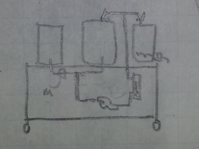
The meter (M) would only be between the RO tank (HLT) and the tee that attaches to the RIMS loop. That line would be fresh water only. You could put a check valve in behind it to prevent the pump from pushing wort back into the RO tank, if the pressure dictated. Simple drawing:

2014-04-18 08.17.58.jpg
 
Back
Top