Wig and Electricity are poor bed fellows (Help please!)

Homebrew Talk - Beer, Wine, Mead, & Cider Brewing Discussion Forum

Help Support Homebrew Talk - Beer, Wine, Mead, & Cider Brewing Discussion Forum:

This site may earn a commission from merchant affiliate links, including eBay, Amazon, and others.

MuddyCreek

Well-Known Member
Joined
Aug 30, 2012
Messages
791
Reaction score
458
Location
Butte
Ok, has ANYONE actually gotten a MyPin TD4 upd and working? I swear at the end of this saga I'm going to write up a layman's guide for getting these things working if I ever manage it.

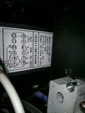
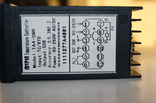
Ok, the image (assuming it came through) is from the TA4, but the TD4 wiring guide is exactly the same. (The TD4 includes a manual mode supposedly... that's if the darn thing ever works.) btw image came from Kal's site. Thanks for the opportunity to pirate! (however unsuccessfully.)

mypin_component_926.jpg


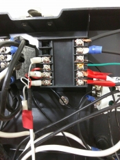
Below are the permutations of how I have attempted to connect wires to this thing in order to get it to work. Nothing seems to although the unit appears to be working correctly with the thermometer etc. It simply isn't sending out any signals to the alarm or the SSR connection.

I would post pictures but at this point everything is disconnected and I'm ready to start from scratch, hopefully correctly... Here goes.

1: white neutral
2: black feed
3 white neutral out to SSR
4 black feed out to SSR
5 white neutral to alarm light
6 black feed to alarm light
7 red line from thermoprobe
8 blue line from thermoprobe

Based on what I've read this seems to be the right way to do this.

I also had black and white lines going from the SSR to my outlet which hopefully one day will control the pump.

Power on the unit. Set it's alarm and set points such that both the output 1 (ssr) and alarm1 lights go on in the unit which SUPPOSEDLY indicates that power is being sent to those units.

The tester confirms that no power is going out to those leads whatsoever. AHA you say... bad unit. I thought about that, of course and tried my OTHER MyPin TD4 and it behaves in exactly the same way. neither the SSR out nor the Alarm1 out appear to have any power going out.

I also tried to swap the white and black lines on the 1 and 2 post as well as swapping all the white and black lines on the outputs. No matter what combination I do, nothing seems to work. For giggles, I connected the white and black directly to the SSR input. It's getting power but nothing is coming out the other side.

I'm not very clear on how to hook up the SSR obviously but it seems not to matter too much since I can't get any power to it from the TD4 anyway.

Can anybody provide any insight about what I'm doing wrong here? It seems like hooking the darn thing up shouldn't be quite so complicated. Any help at all would be appreciated.

Thanks in advance.
 
The back side has two 110 outlet pairs, one of which is set on a simple switch, the other goes through the 3-way. Auto = PID control, ON = well... on.
 
So just to confirm everything:
1) The unit powers up = 1 & 2 are connected right
2) the correct temp is displayed = 8 & 9 are correct (and you have a thermocouple probe)
The problems I see with what you discribe are:
Alarm) this is a realy so what you need to wire is: hot to 5, 6 to one side of your alarm, the other side of the alarm to neutral - It is a switch and will not provide power just let power get to where you want it.
SSR) How are you checking this is working? It should be a 5vDC(?) output, have you got the meter set to measure DC voltage?
 
Matt, Unit powers up fine and the thermoprobe connections are on 7 and 8 and seem to work just fine. I switched to farenheit on the unit and tested the probe in icewater and just-boiled water and the probe seemed to be in the ballpark. I'll calibrate when I have everything up and running properly.

I managed to get the SSR working tonight. Apparently the information on the side of the unit is incorrect. It says 3 is negative and 4 is positive. (The chinese attempt at english directions in the 4 page instructions sent with the controller show a different model with the connections to 3 and 4 reversed. When I did that I got enough voltage from the unit to kick off the SSR.

Your information about the alarm may be what I need to finish the darn thing up. I was running hot and neutral out of the unit to hot and neutral of the alarm (neutral from the alarm continued to the neutral circuit making the rounds.) I will try it as you've suggested. If that works I will have gotten the darn thing working and I really really appreciate it.
 
The TD4 has only 10 contacts opposed to the 12 shown in the diagram. I see there is a connection between contact 6 and 12 on the diagram. I assume this is a reference to the Alarm 2 output at 12 for the model they are showing.

If that follows, I will test contact 10 when Alarm 2 is triggered and see if the feed from contact 5 is being allowed to flow through 10. If that's the case then I will have figured out how Alarm 1 and 2 are set up. Then I just need to fiddle with the manual output settings on the PID itself and determine how to control the BK boil in manual mode. At that point, I think my "Complete Electricity Moron's Guide to the TD4 Controller" will be ready to author.
 
Definitely want to run your TC to 8 and 9 if the diagram in your first post is correct. 7-9 would be for an RTD. Make sure you program your PID so it knows which style of probe is connected.
 
I will swap the connections on the TC and let everyone know how that goes. Appreciate any and all input.
 
SUCCESS!

I got the pump-side PID working tonight. The info from the board helped me a great deal and I truly appreciate it. I put the TC in some ice-water and moved back and forth to a cup of just-boiled water and my alarm, and pump outlet worked just fine.

Changed the P value to 'off' so the relay is either ON or OFF and the pump outlet works precisely as it should.

The pump-side was the more complicated side since I added extra outlets (Yooper!) and switches in order to run aforementioned outlets in auto/on/off mode. The heat side main switch will only route through the PID and ssr. I plan on using the same controller for the HLT and then switching the heating element plug over to the BK element. Then I'd move the set point up to 202 (boil point at my altitude) and wait until I got my boil, then switch to manual mode and drop the % down so I could maintain a gentle boil.

That's the plan anyway.

At any rate, I'll post more photos when it's finished and I DID start "The Complete Electronic Moron's Guide to the TD4" which I hope will make the MyPin TD4 controllers more user-friendly to folks like me who are challenged when it comes to wiring diagrams etc.
 
Great news on your success! Glad you gleamed some form of assistance from the boards, and good luck on writing your post to pay-it-forward.
 
I updated in another thread, but the heat side is finished too. Did a test run and ended up throwing together an ad-hoc batch this afternoon to play.

Everything worked very well. I'm quite pleased. I'll post photos etc in a day or two.
 
I don't know. I will look.

If not I will open up my old box take a photo and try to remember how it was all wired up. Hopefully that will shed light on it for everyone.

I DID get it working. However I haven't used that controller for awhile now. Nonetheless, I found the guide, worked through the crazy, poorly written directions and got the thing wired up correctly.

Will post within the next day or two. Sorry about the delay.
 
Ah, and I just took the photos and was uploading them today.

So, I'm glad you got yours working. Here's what I know. (a very little I'm afraid.)


The two images (assuming they show) are from my now ancient toolbox control panel. I got the mypins working on them using jumpers on 8 and 9 pins, I believe for the thermocouples. Hopefully between the photo and my explanation you guys can work it out...

The thermo side goes as follows for a 3 wire couple.

The thermo wires go on pins 7, 8, 9 and 10 with a jumper between pins 8 and 9.

Power side goes like this... (Far as I can remember...)

1 to alarm
2 to power source
3 to SSR +
4 to SSR -
5 to power source
6 to alarm

It should be noted that this is NOT how the picture on the side of the box says to wire this thing. ;- )

However it did work this way. I had to dig around through a ton of archaic reference sources etc. to find out how to get it working. This worked for me, I hope this is somehow helpful to somebody else.

Sorry about the ugly state of my junk. I did post about this originally in the "my ugly junk thread" so it's all good. Now the terminals are corroded as it hasn't been used in over 2 years. However ugly as it was it worked faithfully for a couple years for me. I originally wired my box up differently. I ran a 22 line directly in and then a separate 110 line as well. I wired outlets off the 110 for running a separate pump etc. and ran ONLY my heating elements and the brewing side off the 220 line. A bit more of a hassle, but in the end worth it.

I also rigged up a fan from a computer, hacked apart an old phone charger for power and got a cooling fan inside the toolbox to help the heat-sinks to keep things chilly in there.

Anyway. Sorry for the delay. I'm always too busy. I do hope this is somehow helpful.
 
No worries! Thanks for sharing. Yes, I found that the polarity was reverse of the diagram on the unit for the DC out to the SSR.

-k
 
Back
Top