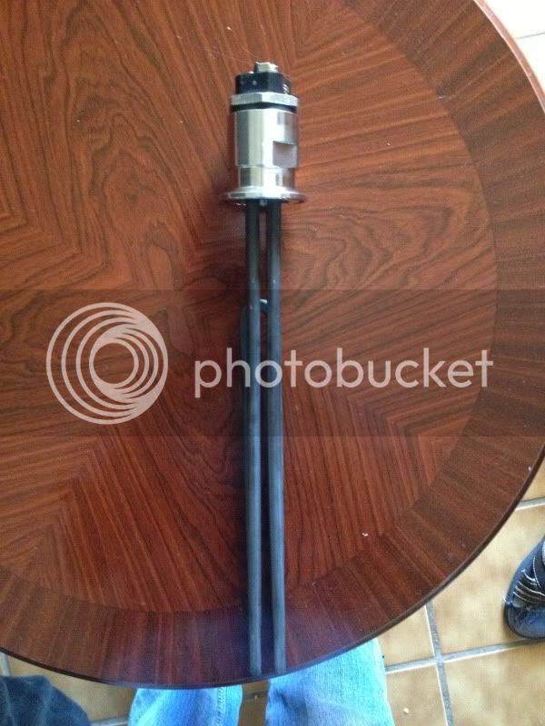
Even if I managed to bend the element, the small size of it won't work in my system. I should have paid attention to the measurements before blindly purchasing it.
So here are a list of replacement elements. Again, I am running 120v.
http://bostonheatingsupply.com/SP10868GL.aspx
These were recommended, but they are 240v, which I can't run on my system right?
http://www.homedepot.com/p/Camco-55...r-Heater-Element-15597/100150507#.UXgPRYKhQmI
http://www.plumbingsupply.com/images/water-heater-element-02933.jpg
The Boston 120V/2000W would be fine, but a tad on the high side and may cause some scorching. Most people use 1500W elements. The 240V/5500W is way overkill and will certainly scorch your wort. It's more meant for a HERMS system or an eKettle.